Recording medium transport device, recording device, and liquid ejecting apparatus

a technology of recording medium and transport device, which is applied in the direction of transportation and packaging, thin material processing, article separation, etc., can solve the problems of reducing the amount of paper transported, deteriorating recording quality, and inability to solve problems, so as to prevent the deterioration of paper feed accuracy

Inactive Publication Date: 2010-03-16
SEIKO EPSON CORP
View PDF9 Cites 5 Cited by
  • Summary
  • Abstract
  • Description
  • Claims
  • Application Information

AI Technical Summary

Benefits of technology

[0016]The invention is made in the light of such a problem and the object is to prevent the deterioration of paper feed accuracy, in particular, the occurrence of transport loss when the back end of a recording paper is passed between a transport driving roller and a transport driven roller (nip point).
[0018]According to the aspect, the angle α is reduced by the adjust means before the back end of the recording medium is passed through the nip point of the transport driving roller and the transport driven roller, so that the difference of a recording medium transport amount with respect to a predetermined rotation amount of the transport driving roller becomes small before and after the back end of the recording medium is passed through the nip point of the transport driving roller and the transport driven roller. Consequently, the deterioration of transport accuracy (occurrence of transport loss) when the back end the recording medium is passed through the nip point of the transport driving roller and the transport driven roller can be prevented.
[0020]According to the aspect, the adjust means sets the angle α to zero before the back end of the recording medium is passed through the nip point of the transport driving roller and the transport driven roller, so that the difference of a recording medium transport amount with respect to a predetermined rotation amount of the transport driving roller becomes further small before and after the back end of the recording medium is passed through the nip point of the transport driving roller and the transport driven roller. Consequently, the occurrence of transport loss when the back end of the recording medium is passed through the nip point of the transport driving roller and the transport driven roller can be more surely prevented.
[0023]Consequently, in the aspect, a transition segment is set before and after the timing when the back end of the recording medium is passed through the nip point of the transport driving roller and the transport driven roller figured out by the control means and the set value of the angle α is switched from α1 to α2 in a stepwise fashion in the transition segment. Accordingly, even when the timing when the back end of the recording medium is actually passed between the transport driving roller and the transport driven roller is not matched to the timing figured out by the control means, the angle α is already changed to an appropriate angle when the back end of the recording medium is passed between the transport driving roller and the transport driven roller. This enables to reduce transport loss when the back end of the recording medium is passed through the nip point of the transport driving roller and the transport driven roller.
[0025]According to the aspect, the control means adjusts the angle α in accordance with the type of the recording medium, so that the posture when the recording medium is nipped by the transport driving roller and the transport driven roller can be adjusted to an appropriate posture in accordance with the thickness / stiffness of the recording medium.

Problems solved by technology

As a result, there is a case in that the recording quality is deteriorated.
However, in the printing device described in Patent Document 1, the problem that the paper transport amount is reduced is unavoidable when the back end of the recording paper is passed through the nip point of the transport driving roller and the transport driven roller. FIG. 8 is a side view of the paper transport pathway for illustrating the problem.
Consequently, it has been impossible to solve the problem.

Method used


Image

  • Recording medium transport device, recording device, and liquid ejecting apparatus
  • Recording medium transport device, recording device, and liquid ejecting apparatus
  • Recording medium transport device, recording device, and liquid ejecting apparatus

Examples


Embodiment Construction

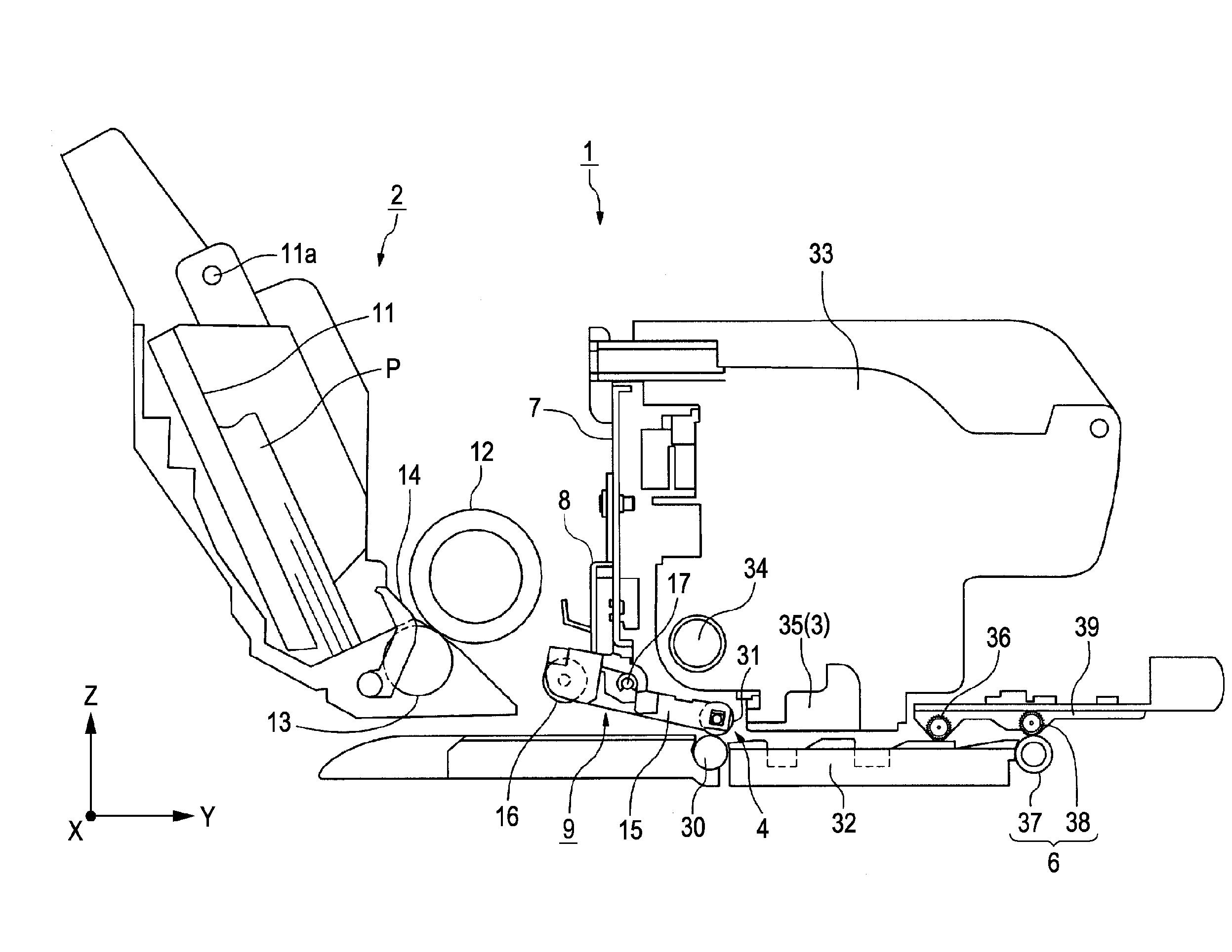
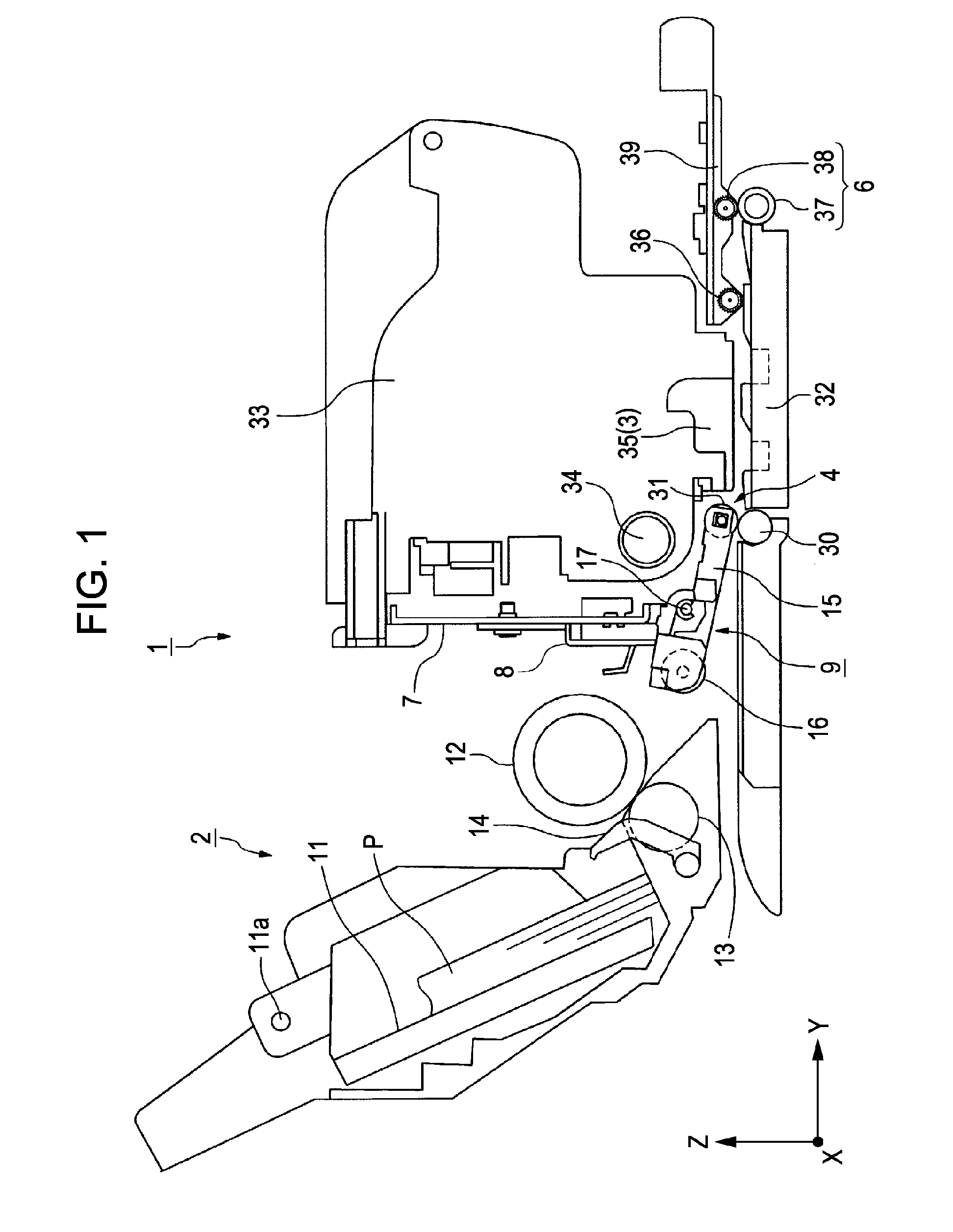
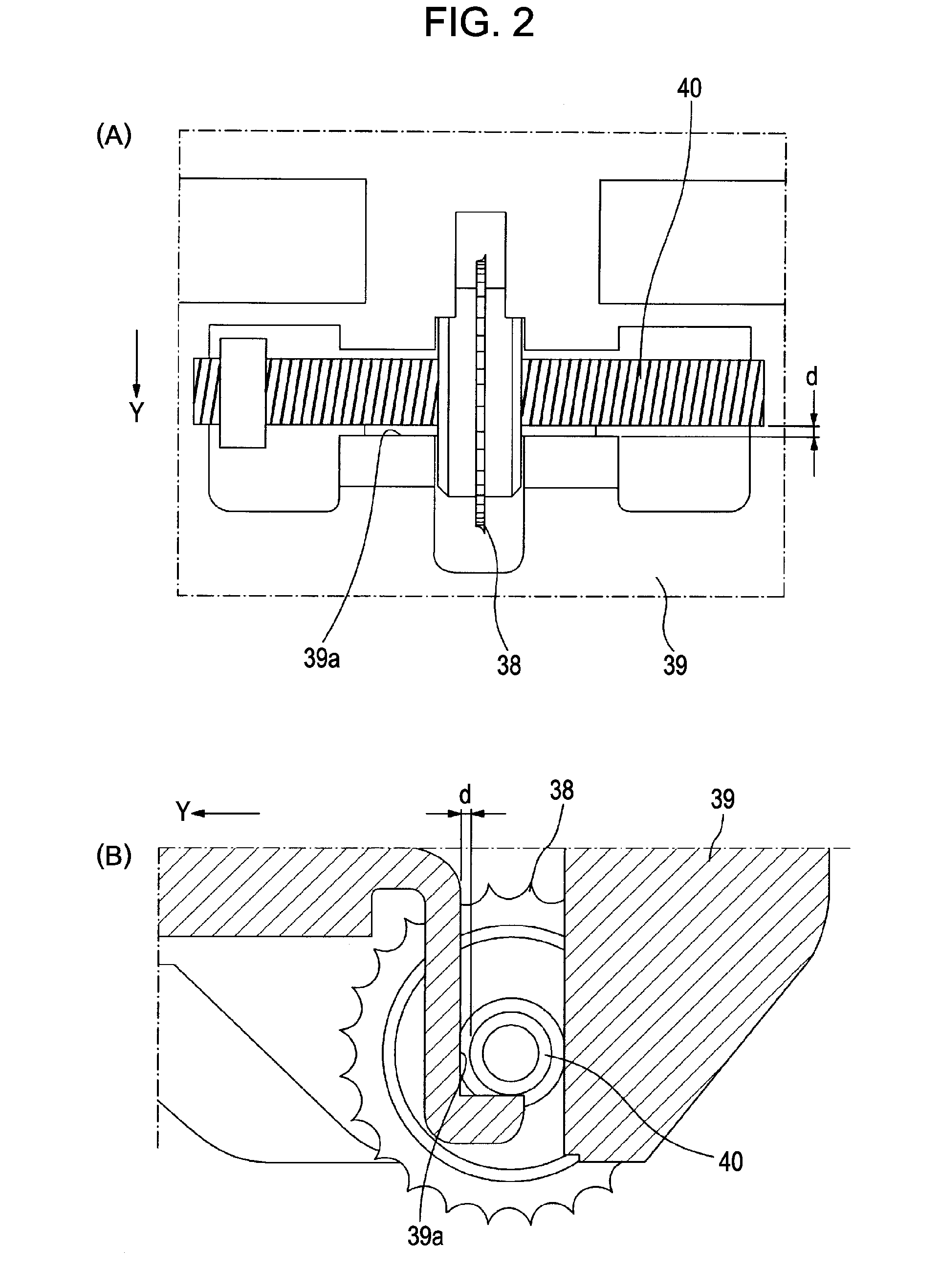
[0036]Hereinafter, an embodiment of the invention will be described with reference to FIG. 1 to FIG. 7. FIG. 1 is a sectional side view of an ink jet printer (hereinafter, referred to as a “printer”) according to an embodiment of a “recording device” or “liquid ejecting device” of the invention, FIG. 2(A) is a plan view of an attachment portion of a discharge driven roller 38, FIG. 2B is a sectional side view of the attachment portion, FIG. 3 is a perspective view of transport means as a “recording medium transport device” of the invention, FIG. 4 is a side view of a paper guide up unit 9 (including a block diagram of a control system), FIG. 5 and FIG. 6 are each a side view of adjust means 26B, FIGS. 7(A), 7(B) are diagrams showing change of a set value of an angle α. Note that, in the coordinate system shown in FIG. 1 and FIGS. 4 to 6, the Y direction shows paper transport direction, the X direction shows paper width direction, and the Z direction shows the direction perpendicular...


PUM


Abstract

A paper guide up unit pivotally supporting a transport driven roller making contact with a transport driving roller is provided so as to be able to be displaced by the rotation of cams. The angle α made by a straight line passing the rotation axis line position of the transport driving roller and the rotation axis line position of the transport driven roller when viewed from the paper transport pathway side and a straight perpendicular to the paper transport direction is changed by the displacement of the paper guide up unit. Control means for controlling the displacement operation of the paper guide up unit reduces the angle α before the paper back end is passed through the nip point of the transport driving roller and the transport driven roller.

Description

BACKGROUND[0001]1. Technical Field[0002]The present invention relates to a recording medium transport device for transporting a recording medium in a recording device, and a recording device and a liquid ejecting apparatus equipped with the same.[0003]Herein, the liquid ejecting apparatus is not limited to a recording device such as a printer, a copier, a facsimile, or the like in which an ink jet type recording head is used and for performing recording on a recording medium by ejecting ink from the recording head, and is used to include an apparatus which ejects liquid corresponding to the application instead of ink from a liquid ejecting head corresponding to the ink jet type recording head on a medium to be ejected corresponding to the recording medium to adhere the liquid on the medium to be ejected.[0004]As the liquid ejecting head, besides the recording head, there are included a color material ejecting head used for manufacture of a color filter such as a liquid crystal displ...

Claims


Application Information

Patent Timeline
Patent Type & Authority Patents(United States)
IPC IPC(8): B65H5/02
CPCB65H5/062B65H2404/14211B65H2511/20B65H2511/21B65H2701/1313B65H2801/06B65H2220/01B65H2220/02B65H2220/11
Inventor ISHIHARA, KENJIROSAITO, KAZUOUENO, KOHEI
Owner SEIKO EPSON CORP
Why Eureka
Try Eureka