Programmable remote control electrical light operating system

a technology of operating system and remote control, which is applied in the field of control system, can solve the problems of not being able to disclose, the device does not appear to disclose an apparatus or a method for the remote control, and the homeowner spends time and effort, and achieves the effect of convenient use and convenient us

Inactive Publication Date: 2010-03-16
WILLS MICHAEL H
View PDF12 Cites 89 Cited by
  • Summary
  • Abstract
  • Description
  • Claims
  • Application Information

AI Technical Summary

Benefits of technology

[0013]The programmable remote control electrical operating system provides a convenient, easy to use way to control multiple electric candles in multiple window settings.

Problems solved by technology

Unfortunately, each individual candle must be turned off and on manually.
This expends time and effort on the part of the homeowner.
This apparatus does not appear to disclose a timer for controlling the individual light assemblies, does not appear to disclose a frequency learning pushbutton for each light assembly, does not disclose a system or apparatus for the control of alternating current powered assemblies nor does it appear to disclose a system for the control of electrical window candle displays.
This device does not appear to disclose an apparatus or method for the remote, wireless control of a plurality of electric window candles.

Method used


Image

  • Programmable remote control electrical light operating system
  • Programmable remote control electrical light operating system
  • Programmable remote control electrical light operating system

Examples


Embodiment Construction

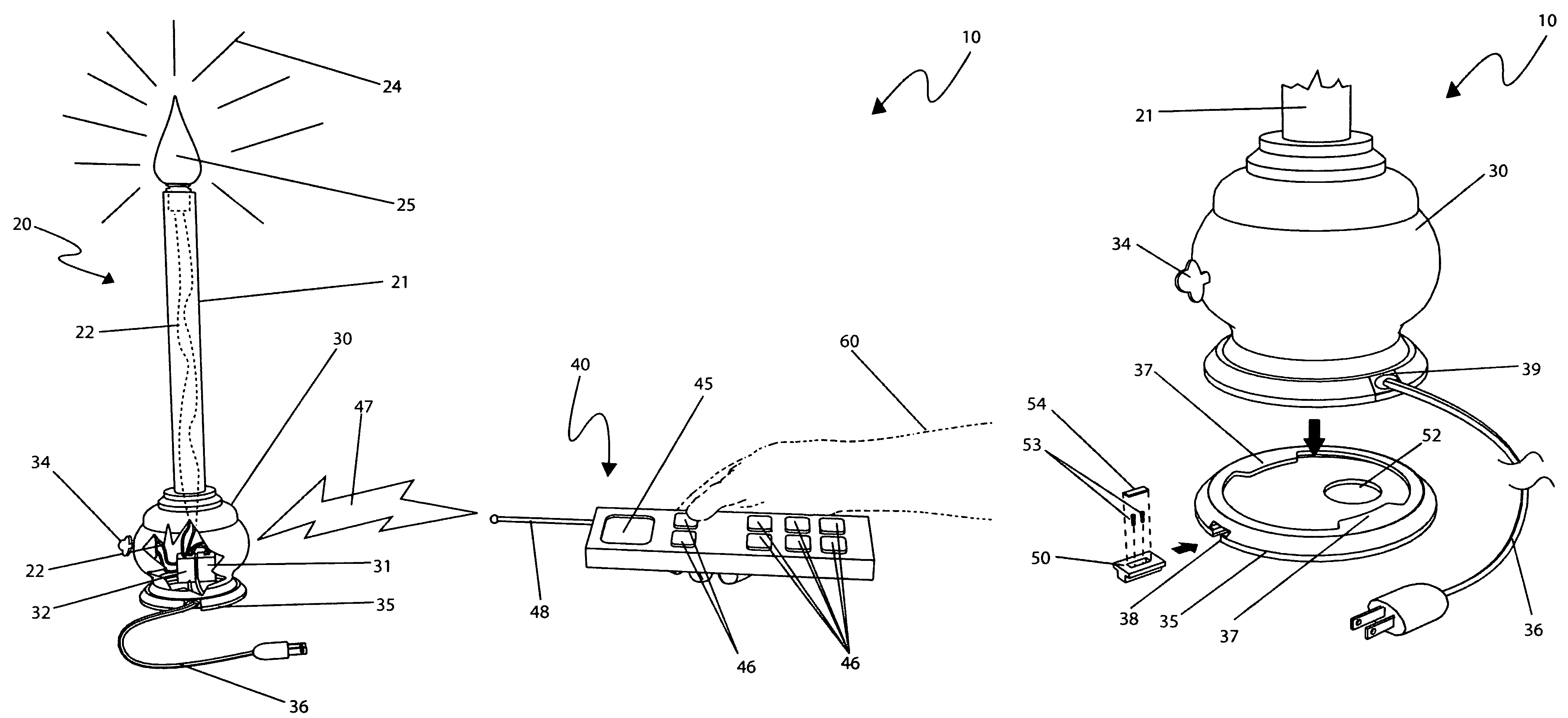
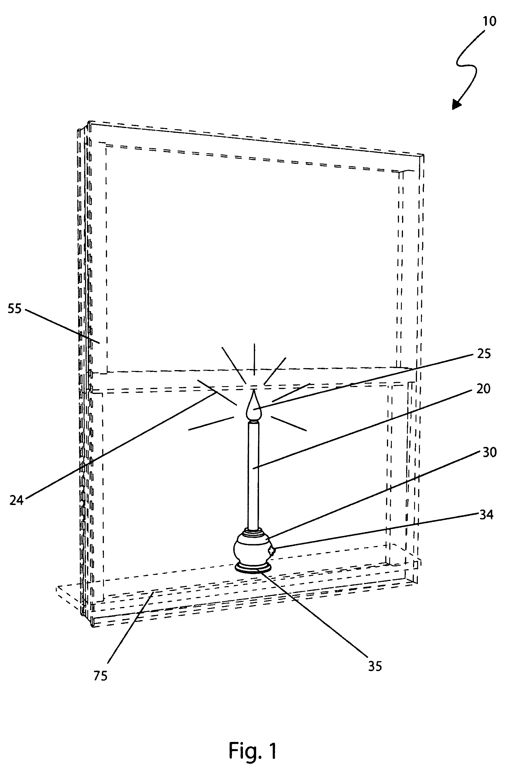
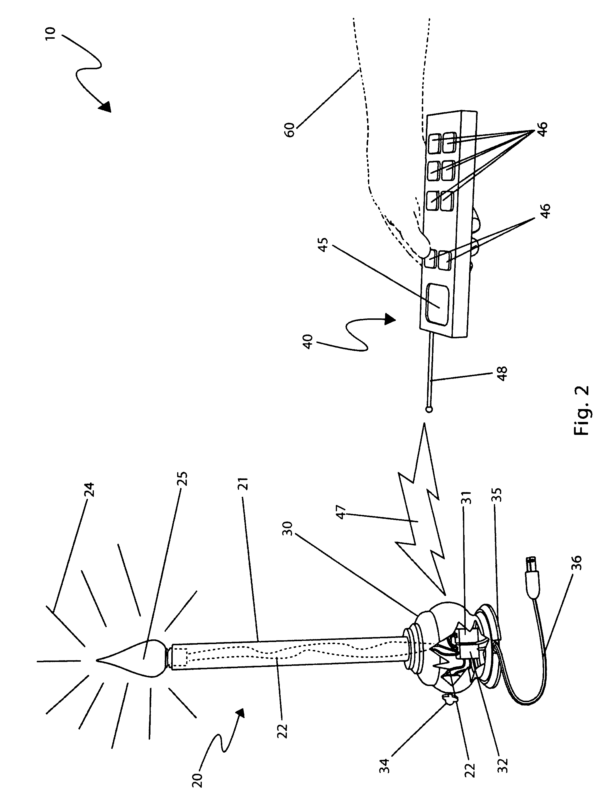
[0057]The best mode for carrying out the invention is presented in terms of its preferred embodiment, herein depicted within FIGS. 1 through 3. However, the invention is not limited to the described embodiment and a person skilled in the art will appreciate that many other embodiments of the invention are possible without deviating from the basic concept of the invention, and that any such work around will also fall under scope of this invention. It is envisioned that other styles and configurations of the present invention can be easily incorporated into the teachings of the present invention, and only one particular configuration shall be shown and described for purposes of clarity and disclosure and not by way of limitation of scope.

[0058]The terms “a” and “an” herein do not denote a limitation of quantity, but rather denote the presence of at least one of the referenced items.

[0059]The present invention describes a device and method for a programmable remote control electrical o...


PUM


Abstract

A control system for turning conventional AC electric window lights on and off particularly during the holiday season by means of a central, wireless remote control is herein disclosed. Specifically, the apparatus provides for the remote control of traditional, electric, window candlelight fixtures. Each lighting fixture has its own integral receiver which responds to on/off commands issued by a programmable remote control transmitter. Each lighting fixture comprises a manual switching means. The remote transmitter is also equipped with frequency learning firmware, a countdown timer, and a conventional timer to allow for the unattended operation of the window lighting fixtures.

Description

RELATED APPLICATIONS[0001]The present invention was first described in and claims the benefit of U.S. Provisional Patent Application No. 60 / 852,271 filed on Oct. 18, 2006, the entire disclosures of which are incorporated herein by reference.FIELD OF THE INVENTION[0002]The present invention relates generally to a control system for turning conventional electric window lights on and off and, more particularly, to traditional, electric, window candles having its own integral receiver that responds to on / off commands issued by a remote, central, wireless transmitter.BACKGROUND OF THE INVENTION[0003]A home decorating idea that has become very popular as of late is the placing of candles in the window. Unfortunately, each individual candle must be turned off and on manually. This expends time and effort on the part of the homeowner. Accordingly, there exists a need for a means by which electric candles used for decorative purposes in windows of a home may be effectively controlled. The de...

Claims


Application Information

Patent Timeline
Patent Type & Authority Patents(United States)
IPC IPC(8): F21V35/00F21L19/00
CPCF21S6/00F21S6/001F21V23/0435F21W2121/00
Inventor WILLS, MICHAEL H.
Owner WILLS MICHAEL H
Why Eureka
Try Eureka