Air exhausting apparatus with draining passage

a technology of air exhausting apparatus and draining passage, which is applied in ventilation systems, heating types, separation processes, etc., can solve problems such as damage to the interior structure of the mounted fan, damage to the units, and damage to the rooms and structures

Active Publication Date: 2010-03-16
CHIEN LUEN INDS
View PDF11 Cites 74 Cited by
  • Summary
  • Abstract
  • Description
  • Claims
  • Application Information

AI Technical Summary

Benefits of technology

[0013]A primary objective of the present invention is to provide an attic and rooftop air exhausting apparatus, device method of assembly, and method for use, for preventing condensation water from entering into the fan housing and into the structure beneath the air exhausting apparatus.

Problems solved by technology

Attic and rooftop fans such as those shown and described in reference to FIG. 1 have been known to become damaged from water intrusion that also damages rooms and structures underneath the locations of such fans.
The water intrusion can come from condensation formed from different temperature conditions and humidity which is a long term problem especially in southern warm and humid climates such as Florida and the southern United States.
In addition rain storms and hurricanes have also caused water to run into these fans which can damage the units as well as cause damage to the interior structures under the mounted fans.
As previously described, the conventional device of FIG. 1 has been known to incur water leakage problems into the room under which it is mounted.
Additionally, water from rain storms and hurricanes, and the like, has also been known to enter into the motor-mounting seat 2 via the air holes 203 and also result in water leakage into the room via the base 1.
Having water leakage can and has resulted in damage to the contents and structures inside the rooms as well as cause health risks from any resulting mold and mildew.
Still furthermore, the water leakage can damage the fan components such as the motor and cause possible short circuits, that can cause fires and other types of damage.
The lifespan of using the conventional outdoor attic and rooftop fans is severely limited since they are susceptible to damage and cannot be expected to work over extended periods of time, especially after storm and hurricane type conditions.
Solutions to try to resolve these problems are generally not practical.
For example, sealing the conventional attic and rooftop fan against water leakage would not work since the fans are required to exhaust air from the structure.
In addition heat from running the fan motor must also be dissipated and any sealing of the fan can result in other damage such as overheating, fire, and the like.

Method used


Image

  • Air exhausting apparatus with draining passage
  • Air exhausting apparatus with draining passage
  • Air exhausting apparatus with draining passage

Examples


Embodiment Construction

[0032]Before explaining the disclosed embodiments of the present invention in detail it is to be understood that the invention is not limited in its applications to the details of the particular arrangements shown since the invention is capable of other embodiments. Also, the terminology used herein is for the purpose of description and not of limitation.

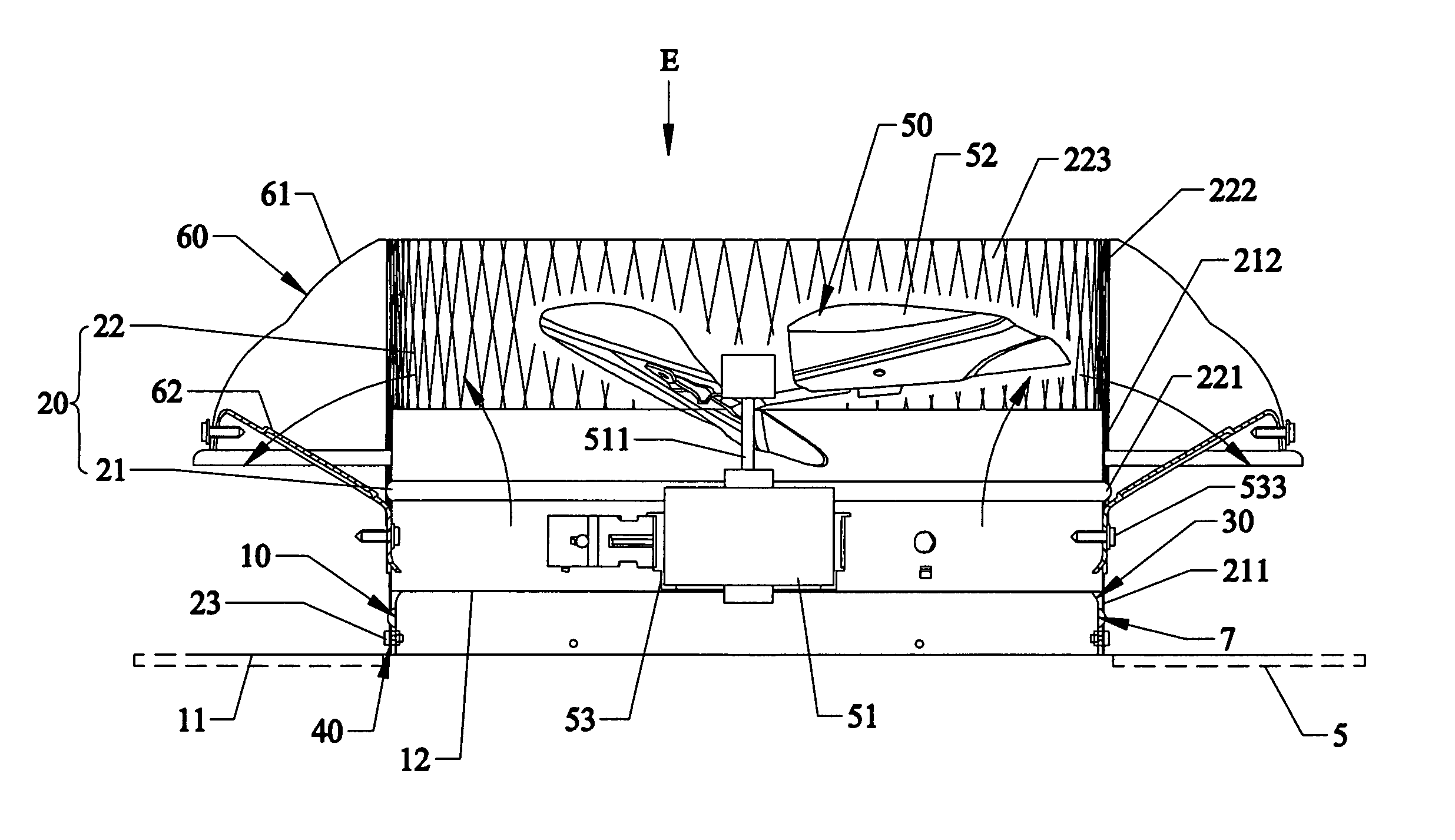
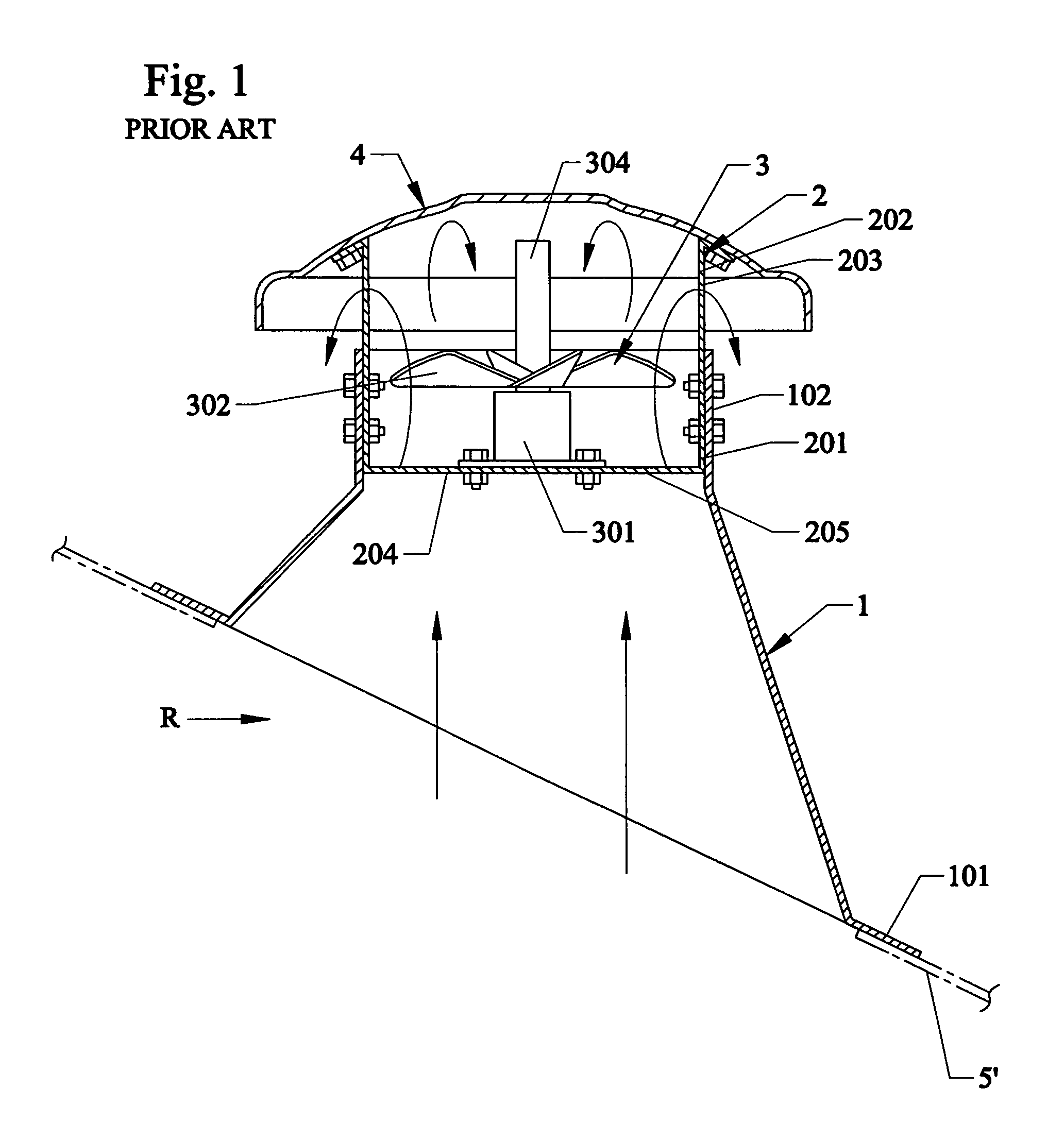
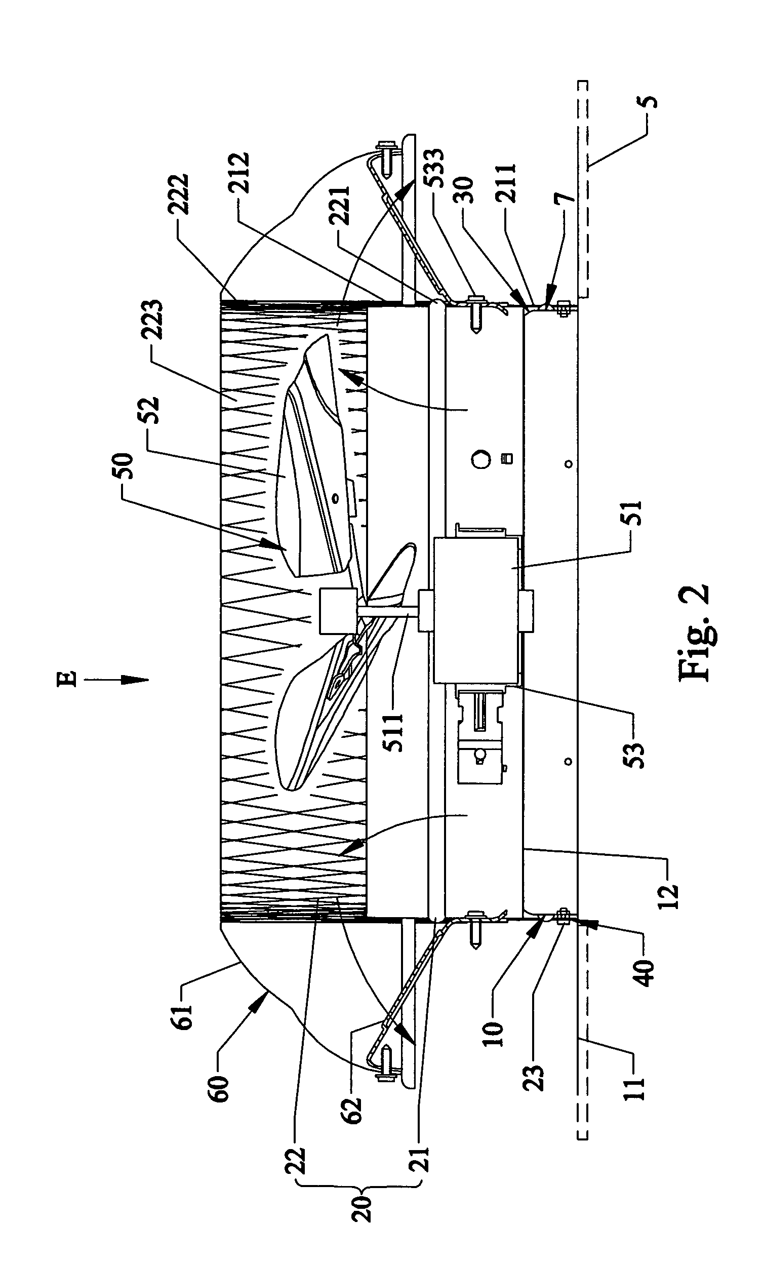
[0033]A list of the components will now be described:[0034]R room[0035]E Invention embodiment[0036]1 tubular base[0037]2 motor mounting seat[0038]3 fan unit[0039]4 cover[0040]5′ roof[0041]7 annular draining passage[0042]10 tubular base (invention)[0043]11 outer extending bottom side of tubular base[0044]12 spider shaped top side (in middle of tubular base 10)[0045]12A arms[0046]12B central support[0047]13 lower end portion[0048]14 upper inwardly bending end portion[0049]20 coupling sleeve unit[0050]21 first sleeve[0051]22 second netted sleeve[0052]23 screw fasteners[0053]30 annular sponge member[0054]40 resilient members[0055]50 fan...


PUM

PropertyMeasurementUnit
sizeaaaaaaaaaa
diameteraaaaaaaaaa
diameteraaaaaaaaaa

Abstract

An air-exhausting apparatus, device, method of assembly and use for an attic and rooftop fan, which prevents water intrusion into the housing. The fan can include a tubular base having a bottom side mounted on a roof of a room, and an upper end portion converging toward a top side of the base. A coupling sleeve unit has a first coupling end portion sleeved fixedly on the base and cooperating with the base to define an annular draining passage therebetween, and a second coupling end portion opposite to the first coupling end portion. A fan unit is mounted in the coupling sleeve unit, and is operable so as to exhaust air outwardly of the room via air holes in the second coupling end portion of the coupling sleeve unit. A cover unit includes a cover body disposed on the second coupling end portion of the coupling sleeve unit, and a supporting frame interconnecting fixedly the cover body and the coupling sleeve unit. Wear and / or sound absorbers can also be included.

Description

[0001]The invention relates to air-exhausting devices such as roof and attic fans, more particularly to an air-exhausting apparatus, devices, systems and methods for preventing water intrusion and for providing drainage passages.BACKGROUND AND PRIOR ART[0002]Attic and rooftop fans such as those shown and described in reference to FIG. 1 have been known to become damaged from water intrusion that also damages rooms and structures underneath the locations of such fans. The water intrusion can come from condensation formed from different temperature conditions and humidity which is a long term problem especially in southern warm and humid climates such as Florida and the southern United States. In addition rain storms and hurricanes have also caused water to run into these fans which can damage the units as well as cause damage to the interior structures under the mounted fans.[0003]FIG. 1 shows a typical and conventional air-exhausting device such as a rooftop or attic fan for exhaust...

Claims


Application Information

Patent Timeline
Patent Type & Authority Patents(United States)
IPC IPC(8): F24F13/20B01D46/00
CPCF24F7/025
Inventor BUCHER, JOHN C.WANG, SHOOUPYNG
Owner CHIEN LUEN INDS
Why Eureka
Try Eureka