Cavity ring-down apparatus and method for measuring reflectivity of highly reflective mirrors

a highly reflective mirror and cavity ring technology, applied in the field of optical component parameters measurement, can solve the problems of difficult to determine the high reflectivity (r>99.9%) of hr coatings using conventional instruments and methods such as spectrophotometers, limited measurement sensitivity and accuracy, and high peak power of pulsed lasers, etc., to achieve accurate measurement of the reflectivity of highly reflective mirrors.

Active Publication Date: 2010-03-16
INST OF OPTICS & ELECTRONICS - CHINESE ACAD OF SCI
View PDF10 Cites 25 Cited by
  • Summary
  • Abstract
  • Description
  • Claims
  • Application Information

AI Technical Summary

Benefits of technology

[0011]In the present invention, a frequency-selective optical feedback from the ring-down cavity is retro-reflected into the oscillator cavity of the semiconductor laser, causing a change in the laser spectrum and an enhancement of the coupling coefficient between the laser power and the ring-down cavity modes.

Problems solved by technology

However, it is difficult to determine high reflectivity (R>99.9%) of HR coatings using conventional instruments and methods such as a spectrophotometer.
However, the use of a narrow-bandwidth laser in their apparatus causes large noise in the cavity output signal and results in a limited measurement sensitivity and accuracy.
However, a pulsed laser with a high peak power, which is often costly and with various complicated optical components, is needed to obtain sufficiently high output intensity from the ring-down cavity.
The spectrum of the laser is occasionally in resonance with one or more eigen-modes of the ring-down cavity, results in rapid increases of the light intensities inside and exiting the ring-down cavity.
One disadvantage of this technique is the low efficiency in the decay time measurement, due to the low probability of spectral resonance.
However, it is costly and complicated because of the use of PZT and AOS.
The use of ECDL and AOM increases the complication of the apparatus.
Although a fast optical switch is not needed, their experimental apparatus, including a tunable ECDL and a PZT, is rather complicated.

Method used


Image

  • Cavity ring-down apparatus and method for measuring reflectivity of highly reflective mirrors
  • Cavity ring-down apparatus and method for measuring reflectivity of highly reflective mirrors
  • Cavity ring-down apparatus and method for measuring reflectivity of highly reflective mirrors

Examples


Embodiment Construction

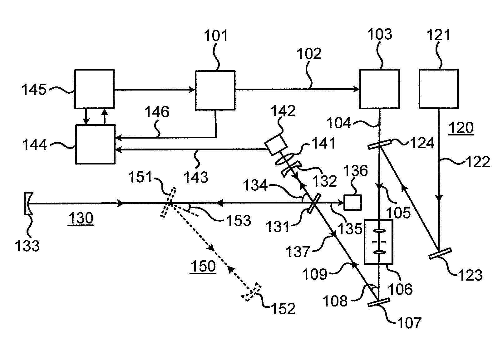
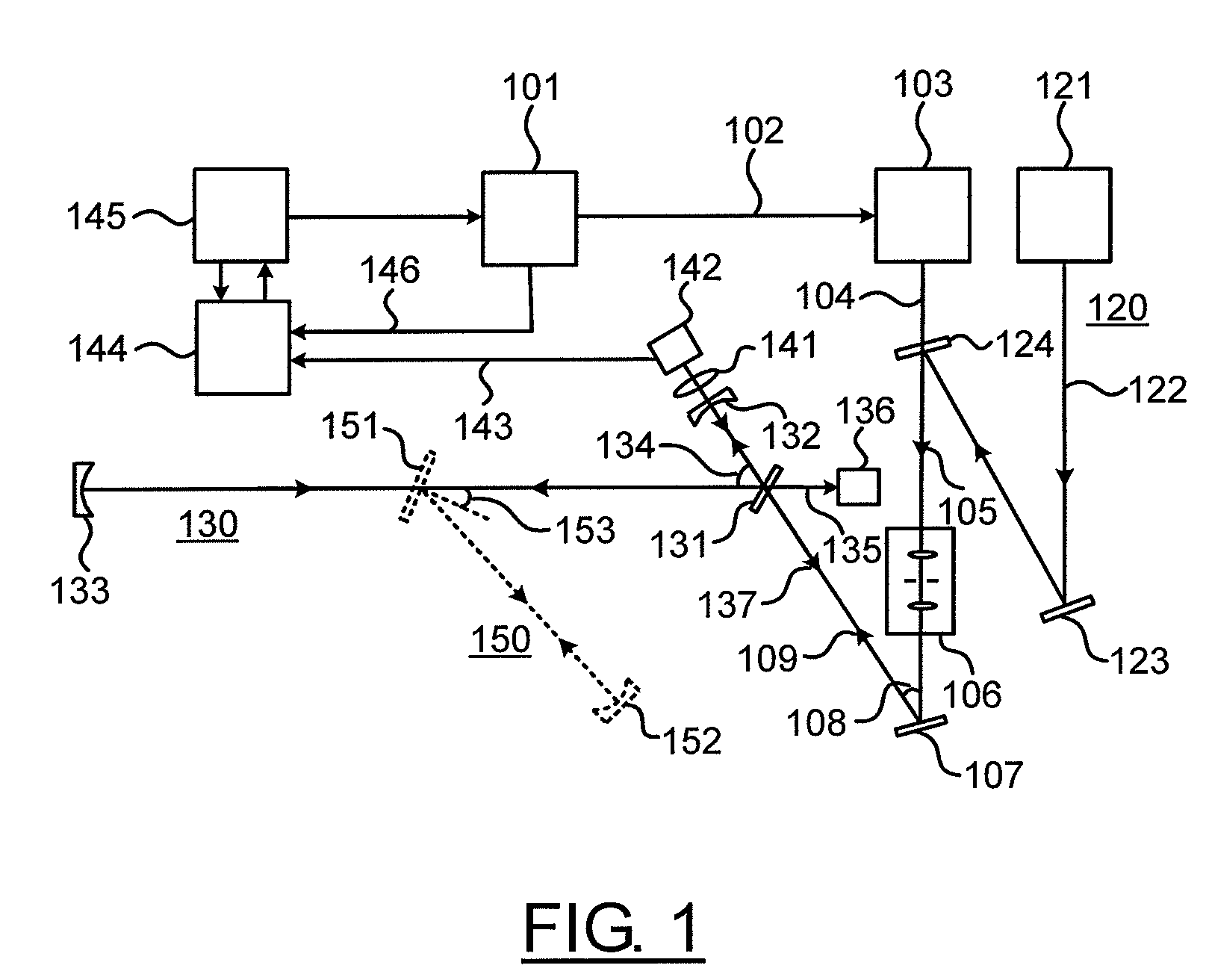
[0022]FIG. 1 illustrates an exemplary embodiment of the present invention. As shown in FIG. 1, a square-wave electric signal 102 is generated from a function generation card 101 and used to modulate the drive voltage of a broad-band (with spectral width above 0.001 nm but less than 10 nm), continuous-wave semiconductor laser 103. A laser beam 104, whose intensity is thus square-wave modulated, is emitted from the semiconductor laser 103. In case the laser beam 104 is visually invisible, a visible beam module 120 is employed for convenience of alignment of the optical arrangement. In this module, a visible light beam 122, generated from a visible light source 121, is adjusted by a reflective mirror 123 and a dichromatic beam splitter 124 to be coaxial with the laser beam 104, making it convenient to precisely adjust the optical components in the optical path of laser beam 104. The combined beam 105 is transmitted through a spatial filter 106, comprising two lenses and a small pinhole...


PUM

PropertyMeasurementUnit
reflectivityaaaaaaaaaa
angleaaaaaaaaaa
angle of incidenceaaaaaaaaaa

Abstract

A cavity ring-down apparatus and method is provided for measuring the reflectivity of highly reflective mirrors. The apparatus comprises an optical ring-down cavity including three highly-reflective mirrors whose frequency-selective optical transmission is retro-reflected into the oscillator cavity of a continuous-wave semiconductor laser, creating a change of output spectrum of said laser and enhancing the coupling coefficient of the laser power into the optical ring-down cavity. The drive current / voltage of the semiconductor laser is modulated by a square-wave function output by a function generation card. Thus the laser beam is suddenly switched off at the negative step of the square-wave signal periodically. Immediately after switching off the laser beam, an exponential decay signal of the ring-down cavity is measured by a photo detector and used to determine the decay time of the cavity and the reflectivity of highly reflective mirrors.

Description

CROSS-REFERENCE TO RELATED APPLICATION[0001]This application claims priority, under 35 USC §119, of Chinese Patent Application No. 200810102778.8 filed on Mar. 26, 2008, the entire contents of which are herein incorporated by reference.FIELD OF THE INVENTION[0002]The invention relates generally to the measurement of the parameters of optical components and, in particular, to the measurement of reflectivity of highly reflective mirrors using a cavity ring-down apparatus and method.BACKGROUND OF THE INVENTION[0003]The film-deposition technology has been developing rapidly in recent years and the performance of thin films, especially the widely used highly reflective (HR) coatings, has been greatly improved. However, it is difficult to determine high reflectivity (R>99.9%) of HR coatings using conventional instruments and methods such as a spectrophotometer. To measure the reflectivity approaching unity, the so-called cavity ring-down (CRD) technique has been employed. It is based o...

Claims


Application Information

Patent Timeline
Patent Type & Authority Patents(United States)
IPC IPC(8): G01N21/55
CPCG01M11/005
Inventor LI, BINCHENGGONG, YUAN
Owner INST OF OPTICS & ELECTRONICS - CHINESE ACAD OF SCI
Why Eureka
Try Eureka