
Distortion compensating amplifier

a distortion compensation and amplifier technology, applied in the direction of transmission monitoring, baseband system details, gain control, etc., can solve the problems of affecting the realization of affecting the normal and high-quality communication. achieve the effect of high-efficiency distortion compensation and highly accurate distortion compensation

Inactive Publication Date: 2010-03-16
KOKUSA ELECTRIC CO LTD
View PDF5 Cites 16 Cited by
  • Summary
  • Abstract
  • Description
  • Claims
  • Application Information

AI Technical Summary

Benefits of technology

The invention is a highly efficient distortion compensating amplifier that can accurately compensate for distortion in main amplifiers. The amplifier has a constitution that includes a first amplifying unit, a second amplifying unit, and a combining unit. The first amplifying unit amplifies a main signal and detects distortion in the first main amplifier. The second amplifying unit amplifies a combined signal with the distortion adjusted by the distortion adjusting unit. The combining unit combines the amplified signals from the first and second amplifying units. The amplifier can achieve highly accurate distortion compensation by independently adjusting the distortion in the first and second amplifiers. The amplifier has a high efficiency and can be used in various applications.

Problems solved by technology

When linearity of an amplifier used for the high-frequency amplification is not sufficiently high, various kinds of distortion such as intermodulation distortion occur.
This distortion hinders realization of normal and high-quality communication.
However, in the conventional cross-cancel system, it is impossible to control a signal and distortion components on the main line separately.
Thus, it is extremely difficult to sets main signal components in the same phase and set the distortion components in opposite phases.

Method used


Image

  • Distortion compensating amplifier
  • Distortion compensating amplifier
  • Distortion compensating amplifier

Examples


Embodiment Construction

[0067]An embodiment according to the invention will be explained with reference to the accompanying drawings.

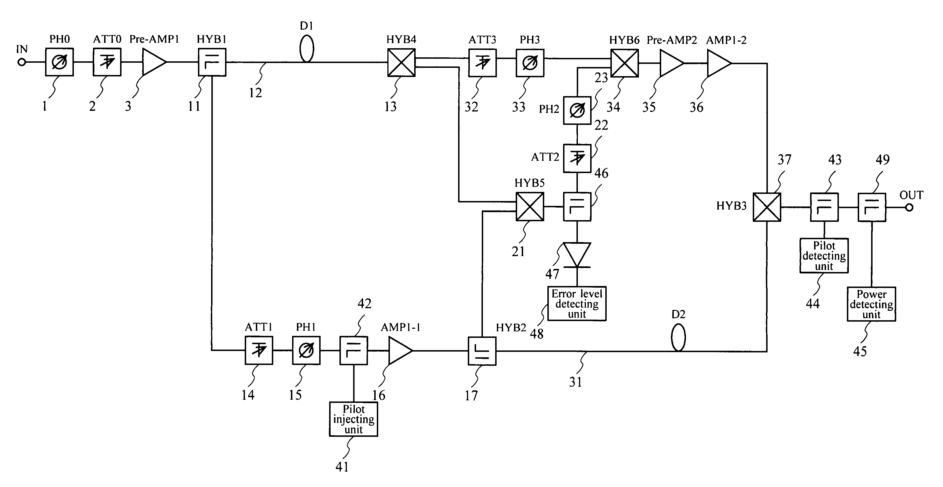
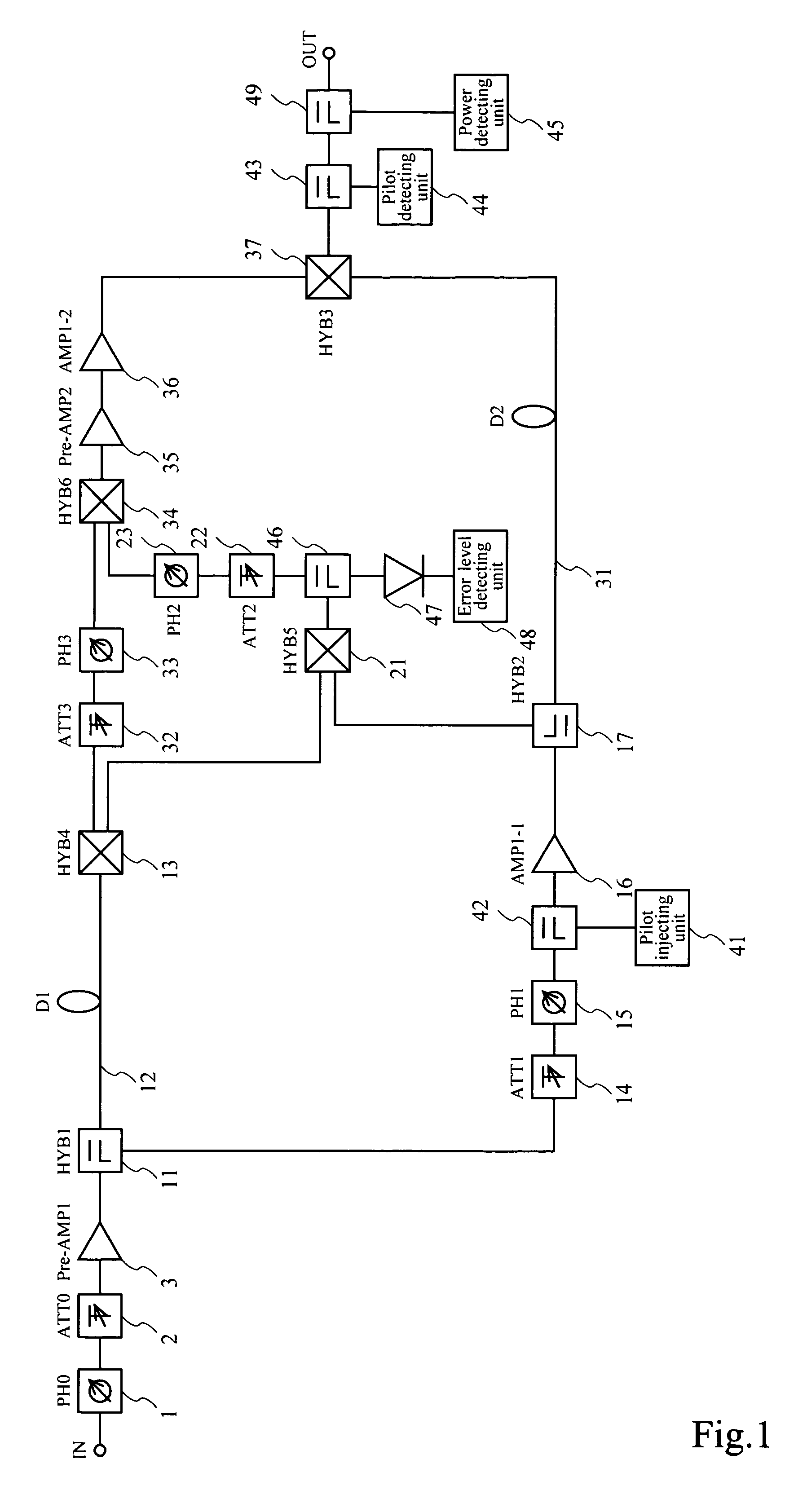
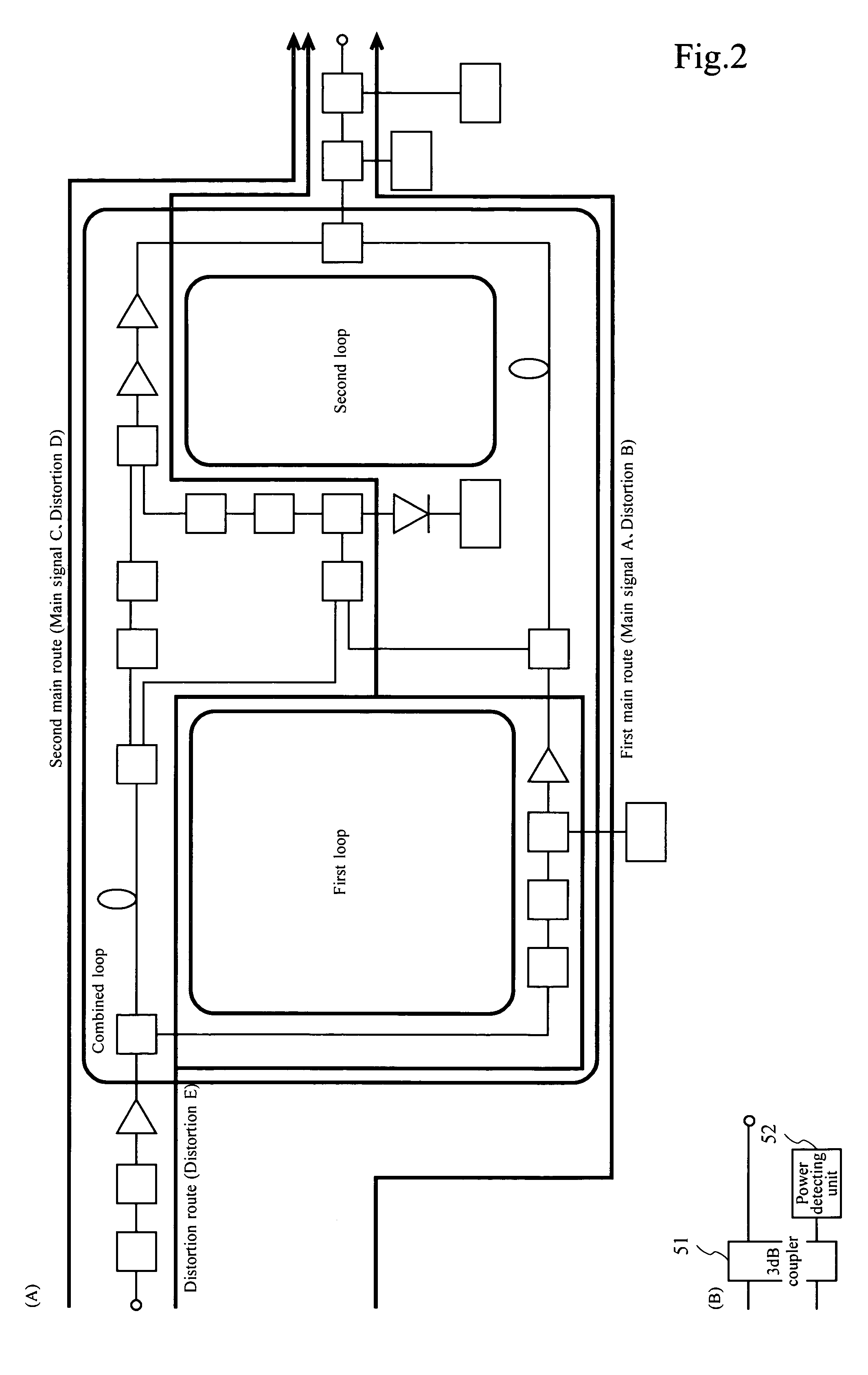
[0068]An example of a circuit configuration of a distortion compensating amplifier in this embodiment is shown in FIG. 1.

[0069]The distortion compensating amplifier in this embodiment includes a variable phase-shifter (a zeroth variable phase-shifter) 1, a variable attenuator (a zeroth variable attenuator) 2, a preamplifier (a first preamplifier) 3, a hybrid (a first hybrid) 11, a coaxial delay line (a first coaxial delay line) 12, a hybrid (a fourth hybrid) 13, a variable attenuator (a first variable attenuator) 14, a variable phase-shifter (a first variable phase-shifter) 15, a main amplifier (a first main amplifier) 16, a hybrid (a second hybrid) 17, a hybrid (a fifth hybrid) 21, a variable attenuator (a second variable attenuator) 22, a variable phase-shifter (a second variable phase-shifter) 23, a coaxial delay line (a second coaxial delay line) 31, a variable attenuator...


PUM


Abstract

In a distortion compensating amplifier that compensates for distortion occurring in main amplifiers, a first amplifying unit amplifies, with a first main amplifier, a first signal consisting of a main signal to be amplified and detects distortion occurring in the first main amplifier, a distortion adjusting unit subjects the distortion detected by the first amplifying unit to vector adjustment, a second amplifying unit combines a second signal consisting of the main signal to be amplified and the distortion supplied from the distortion adjusting unit and amplifies a combined signal with a second main amplifier, and a combining unit combines an amplified signal supplied from the first amplifying unit and an amplified signal supplied from the second amplifying unit.

Description

BACKGROUND OF THE INVENTION[0001]1. Field of the Invention[0002]The present invention relates to a distortion compensating amplifier that compensates for distortion occurring in an amplifier that amplifies a signal, and, more particularly to a highly efficient distortion compensating amplifier that realizes highly accurate distortion compensation.[0003]2. Description of the Related Art[0004]For example, in a base station apparatus and a relay station apparatus for mobile communication, a multi-carrier signal including a large number of carrier waves, which are properly modulated at predetermined frequency intervals, respectively, is transmitted by radio after being subjected to high-frequency amplification. When linearity of an amplifier used for the high-frequency amplification is not sufficiently high, various kinds of distortion such as intermodulation distortion occur. This distortion hinders realization of normal and high-quality communication. Therefore, an amplifier used for ...

Claims


Application Information

Patent Timeline
Patent Type & Authority Patents(United States)
IPC IPC(8): H04B1/04H01Q11/12
CPCH03F1/3223
Inventor ISHIGAMI, TAKESHI
Owner KOKUSA ELECTRIC CO LTD
Learn More