Ice thermal storage

a technology of ice thermal storage and storage capacity, which is applied in the direction of defrosting, lighting and heating apparatus, and domestic cooling apparatus, etc., can solve the problems of affecting the heat produced by rack-mounted equipment can have adverse effects on the performance, reliability and useful life of equipment components, so as to save compressor power and scale up the cooling capacity and storage

Inactive Publication Date: 2010-03-23
AMERICA POWER CONVERSION CORP
View PDF102 Cites 25 Cited by
  • Summary
  • Abstract
  • Description
  • Claims
  • Application Information

AI Technical Summary

Benefits of technology

[0011]Various aspects of the invention may provide one or more of the following capabilities. Equipment can be cooled during power failures using battery power and thermal ice storage. Cooling capacity and storage can be scalable. A simple standardized ice storage unit can be provided. Backup cooling can work in conjunction with pumped refrigerant cooling systems. Ice may be produced using 45° F. chilled water as heat of rejection. Lower evaporating pressure of pumped R134a can be achieved using a vapor pump. The lower evaporating pressure allows an evaporating temperature low enough to freeze water to ice. The main pumped refrigerant system does not normally require temperatures low enough to freeze water and hence does not require low evaporating pressures. The vapor pump enables the system to save compressor power by only lowering the pressure of a portion of the pumped liquid refrigerant beyond that of which the main system would normally require. Ice can be generated using a chilled water loop, while a main external chilled water loop remains at normal operational temperature.

Problems solved by technology

This equipment consumes electrical power and generates heat.
Heat produced by the rack-mounted equipment can have adverse effects on the performance, reliability and useful life of the equipment components.

Method used


Image

  • Ice thermal storage
  • Ice thermal storage
  • Ice thermal storage

Examples


Embodiment Construction

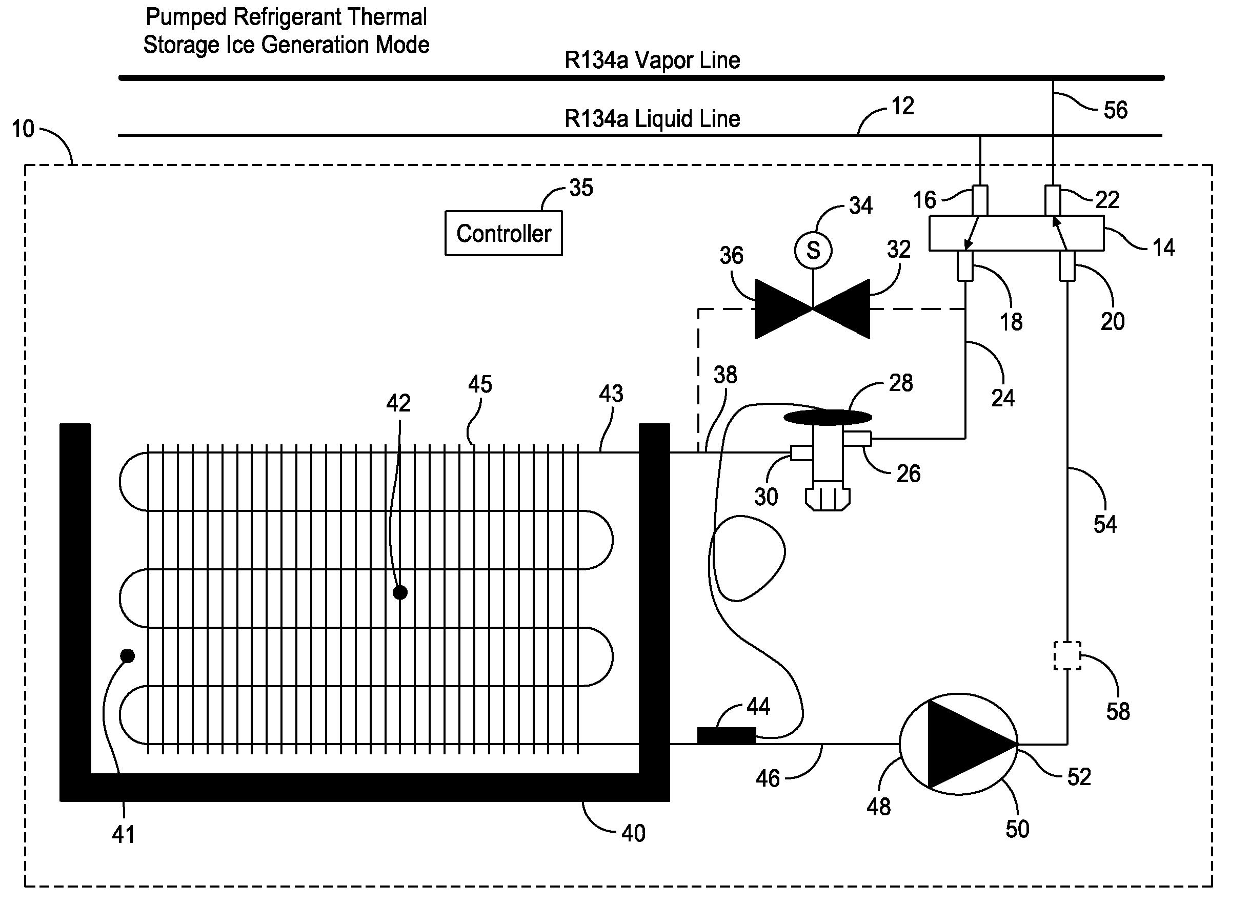
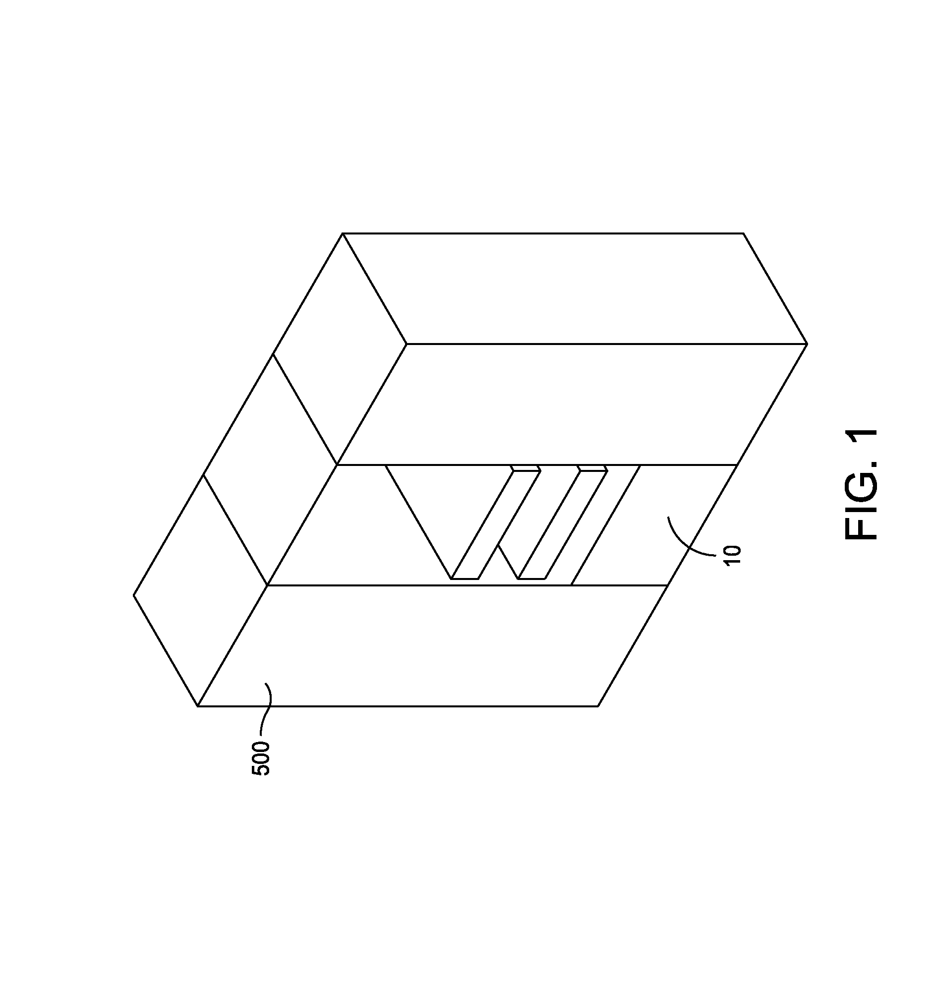
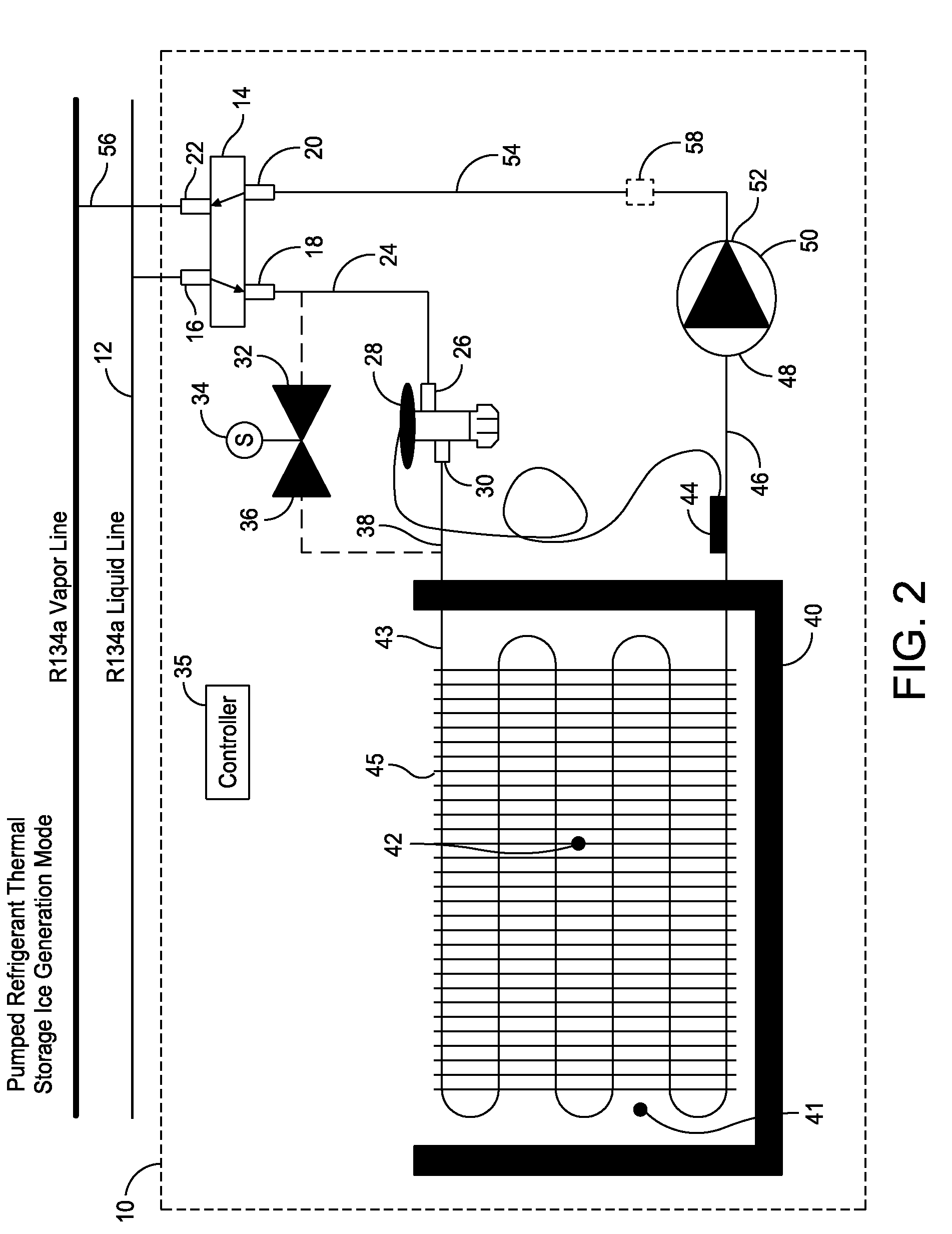
[0022]Embodiments of the invention provide techniques for cooling information technology (IT) equipment while one or more UPSs support the operation of the IT equipment, e.g., during main power failure, or at any other time cooling is desired. An exemplary embodiment of the invention includes a rack-mountable ice / water tank that has a submersed tubular fin coil. The ice / water tank generates and stores ice during normal operation with the IT equipment drawing electric power from building power. During building power failure and UPS operation, the ice / water tank operates as a heat sink for the coolant to remove heat from the IT equipment, e.g., for the duration of the UPS battery life or depletion of ice in the storage system. An exemplary embodiment utilizes a portion of liquid refrigerant from a pumped liquid refrigerant system, which is expanded in the tubular fin coil submersed in the ice / water tank, thereby reducing the water temperature to the freezing point and adsorbing the la...


PUM


Abstract

A system, configured to be disposed in a information technology equipment rack for providing ice thermal storage, includes a tank configured to hold water, a heat exchanger disposed in water in the tank and configured to convey a two-phase liquid and vapor refrigerant and to transfer heat between the water and the refrigerant, a first valve connected to a liquid and a vapor refrigerant line and configured to selectively connect the liquid refrigerant line to a first port and the vapor refrigerant line to a second port in a first mode and to connect the liquid refrigerant line to the second port and the vapor refrigerant line to the first port in a second mode, a thermostatic expansion valve connected to an inlet of the heat exchanger, and a liquid/vapor pump connected to an outlet of the heat exchanger and to the second port of the first valve.

Description

BACKGROUND OF THE INVENTION[0001]Rack-mounted communications and information technology equipment is widely used in today's society. This equipment consumes electrical power and generates heat. Heat produced by the rack-mounted equipment can have adverse effects on the performance, reliability and useful life of the equipment components. Thus, cooling systems are used to cool the equipment.[0002]To help guard against malfunction in equipment due to power failure, uninterruptible power supplies (UPSs) are often used to provide backup power in case of a power outage. UPSs are commonly used on computing equipment to guard against data being lost due to a power outage before the data are saved. UPSs used with computing equipment also help to guard against a loss in service by providers of information over the Internet, such as by servers, e.g., hosting web pages.[0003]Cooling of communications and information technology equipment is desirable during main power failure, and while the equ...

Claims


Application Information

Patent Timeline
Patent Type & Authority Patents(United States)
IPC IPC(8): F25D23/12
CPCF25D16/00H05K7/20818F25B21/02F25B2400/0411F25B2400/24
Inventor BEAN, JR., JOHN H.
Owner AMERICA POWER CONVERSION CORP
Why Eureka
Try Eureka