Sanitary conveyor transfer tail assembly

a tail assembly and conveyor technology, applied in the direction of conveyors, conveyor parts, transportation and packaging, etc., can solve the problems of contamination of the conveyor, intersection of two conveyor sections,

Active Publication Date: 2010-03-23
DORNER MFG. CORP.
View PDF14 Cites 31 Cited by
  • Summary
  • Abstract
  • Description
  • Claims
  • Application Information

AI Technical Summary

Benefits of technology

[0009]Each of the side brackets includes a support notch that receives one end of a cross support member of the transfer tail assembly. Each end of the cross support member includes a retaining slot such that the spaced side brackets engage the retaining slots to prevent the lateral movement of the cross support relative to the longitudinal axis of the conveyor assembly. The slidable engagement between the cross support and side brackets also prevents rotation of the cross support relative to the side brackets.

Problems solved by technology

If the conveyor includes areas that collect water, bacteria can form in the wet areas, which is unacceptable in a sanitary environment.
A significant problem exists at the intersection of two conveyor sections when transferring relatively small articles.

Method used


Image

  • Sanitary conveyor transfer tail assembly
  • Sanitary conveyor transfer tail assembly
  • Sanitary conveyor transfer tail assembly

Examples


first embodiment

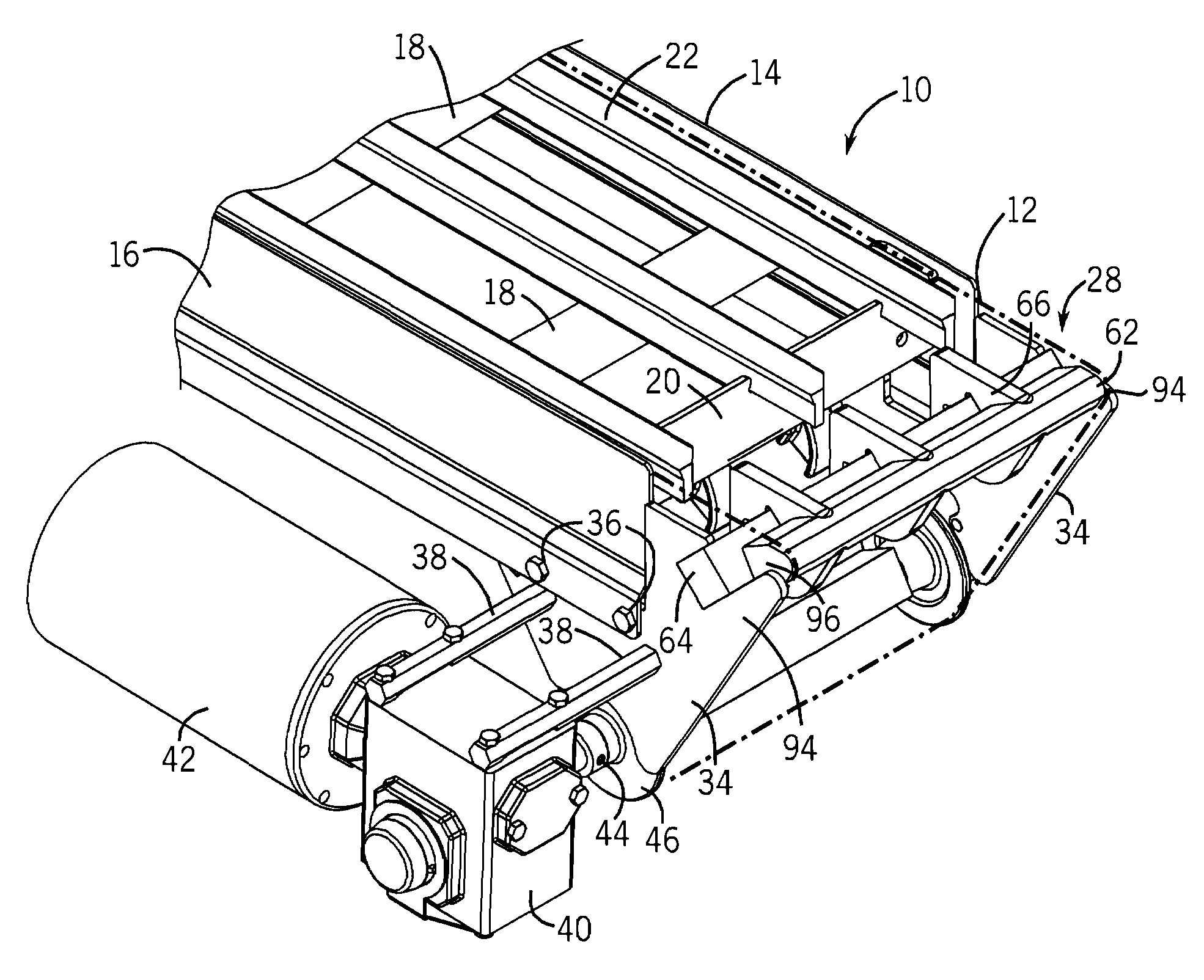
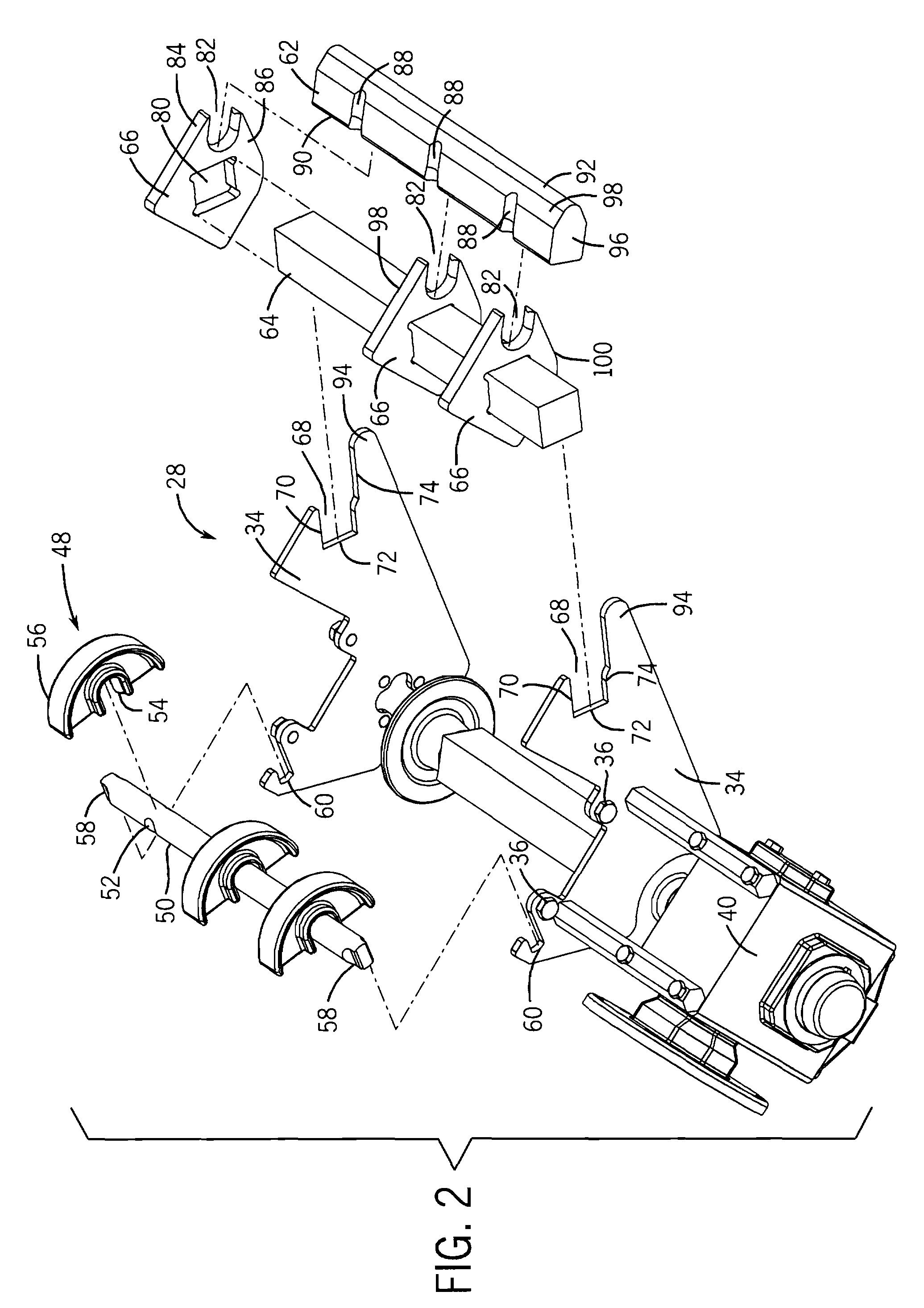
[0026]Referring back to FIG. 1, the transfer tail assembly 28 of the invention includes a pair of spaced side brackets 34 that are each attached to one of the side frame members 14,16 of the conveyor assembly 10. In the embodiment of the invention illustrated, each of the side brackets 34 are attached to one of the side frame members 14,16 by a pair of bolts 36. The side brackets 34 receive a pair of mounting rails 38 that support a gear box 40 and an associated drive motor 42. The gear box 40 receives a shaft 44 that supports a series of spaced drive sprockets, not shown.

[0027]As can be seen in FIG. 3, the conveyor belt 12 passes over the outer surface of the drive sprockets (not shown) such that the drive sprockets impart the driving force required to move the continuous conveyor belt 12.

[0028]The conveyor belt 12 passes over a series of curved idler supports 48 spaced along a shaft 50. As can be seen in FIG. 2, the shaft 50 includes a series of spaced notches 52 that each receive...

second embodiment

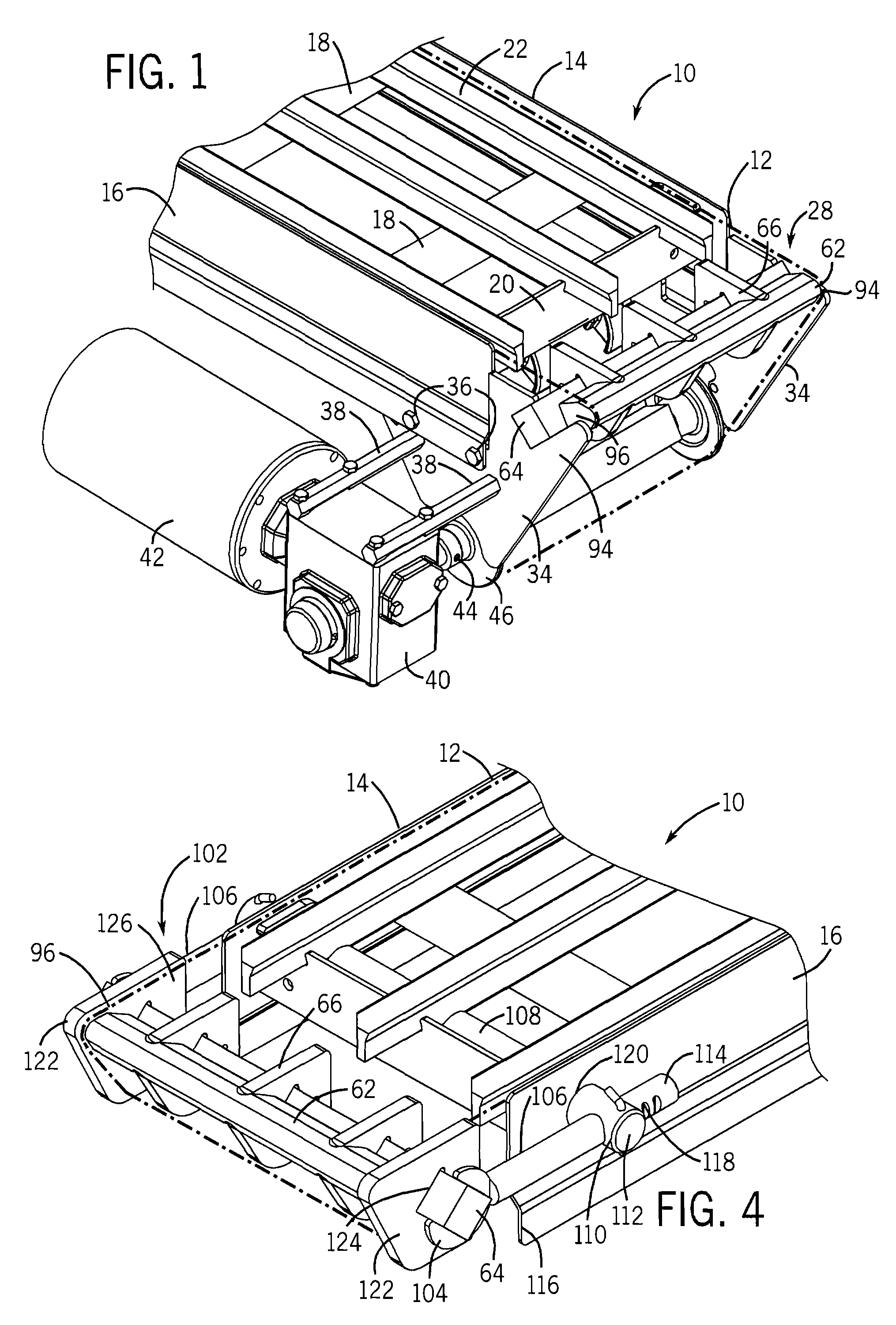
[0042]Referring now to FIG. 4, thereshown is the transfer tail assembly 102 that can be used on the opposite end of the conveyor assembly 10. The transfer tail assembly 102 includes most of the same components as the transfer tail assembly 28 and like reference numerals are used to identify the components.

[0043]As illustrated in FIG. 4, the transfer tail assembly 102 includes the nose bar 62 supported by the plurality of spaced support brackets 66 along the cross support 64. However, the transfer tail assembly 102 includes side brackets 104 each mounted to a side arm 106. Each of the side arms 106 extends through an axle 108. Axle 108 extends across the width of the conveyor assembly 10 through both of the side frame members 14,16. The axle 108 includes a bore 110 near each of its outer ends 112 that allows the respective side arm 106 to extend therethrough. The back end 114 of each side arm 106 extends past the axle 108 and allows the side arms 106 to move generally along the longi...


PUM


Abstract

A transfer tail assembly for use with a conveyor assembly that creates a reduced radius transition from the upper run to the lower run of a continuous conveyor belt used with the conveyor assembly. The transfer tail assembly includes a stationary nose bar over which the continuous conveyor belt passes at the end of the conveyor assembly. The nose bar is supported at the end of the conveyor assembly by a series of support brackets mounted to a cross support. Each of the support brackets is formed from a wear resistant material and contacts the conveyor belt as the conveyor belt passes around the transfer tail assembly. The nose bar, support brackets and cross support are mounted within the tail assembly without the use of any external connectors and thus require no tooling to assemble and disassemble.

Description

BACKGROUND OF THE INVENTION[0001]The present invention generally relates to a transfer tail assembly for a conveyor that is particularly useful in a sanitary environment. More specifically, the present invention relates to a transfer tail assembly that includes a reduced radius transfer point between the upper and lower runs of a continuous conveyor belt and can be completely disassembled for cleaning without the use of any tools.[0002]Presently, in food processing conveyor applications, conveyors must be manufactured such that the conveyor belt can be removed and the entire conveyor frame assembly sanitized. Following sanitation, the conveyor belt must be reinstalled for continued operation. Numerous guidelines exist to regulate the type of conveyor assembly that be used in a sanitary environment, such as in a food processing facility. Typically, these guidelines require that the conveyor frame assembly must be capable of being disassembled and sanitized. Since the conveyor frame a...

Claims


Application Information

Patent Timeline
Patent Type & Authority Patents(United States)
IPC IPC(8): B65G21/00B65G21/06
CPCB65G15/62B65G21/06B65G21/105B65G47/66
Inventor HOSCH, MICHAEL A.HALL, SCOTT M.ERTEL, DANIEL E.
Owner DORNER MFG. CORP.
Why Eureka
Try Eureka