Device for transporting containers

a container and belt technology, applied in the direction of conveyor parts, mechanical conveyors, transportation and packaging, etc., can solve the problems of lateral torsional stress of the belt, further damage to the plant, alignment problems of the operating organs of the machine, etc., and achieve the effect of avoiding torsional deformation of the cogged bel

Active Publication Date: 2010-03-23
MARCHESINI GROUP SPA
View PDF9 Cites 9 Cited by
  • Summary
  • Abstract
  • Description
  • Claims
  • Application Information

AI Technical Summary

Benefits of technology

[0008]The aim of this invention is to obviate the aforementioned drawback by providing a device for in-line transport of containers which makes it possible to avoid torsional deformation of the cogged belt.
[0009]A further aim of the invention is to provide a constructively and functionally uncomplicated transport device which is highly reliable in operation, versatile in use, and relatively inexpensive.
[0010]The abovementioned aims are achieved by means of a device for transporting containers of a type comprising a cogged belt which develops along a ring-wound trajectory and is wound about at least a pair of cogged wheels rotatable on vertical axes, and a plurality of regularly distanced support means borne on an external surface of the cogged belt, which support means receive containers to be transported, characterized in that fixed to an internal surface thereof the cogged belt exhibits a plurality of skates which engage with guide means integral to a fixed structure of the device, in such a way that at least one lateral constraint is provided to prevent transversal shifting and deformation of the cogged belt.

Problems solved by technology

However, a frequent criticism is that the weight of the containers housed in the support means along the belt may induce lateral torsional stress in the belt.
Deformation causes wear, alignment problems for the operating organs of the machine and further damage to the plant.
Obviously the effects of the drawback described may be more or less serious according to the thickness, width and flexibility of the belt, the weight and dimensions of the containers transported, and the distance between the cogged wheels.

Method used


Image

  • Device for transporting containers
  • Device for transporting containers
  • Device for transporting containers

Examples


Embodiment Construction

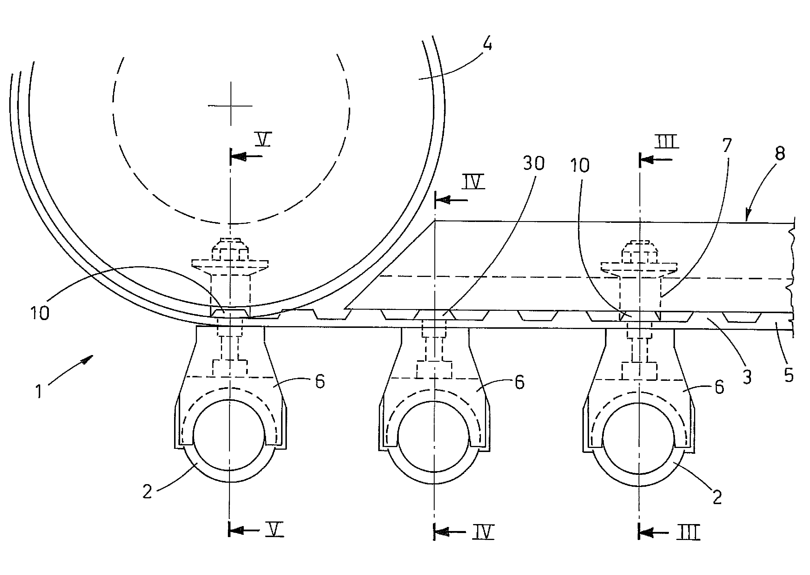
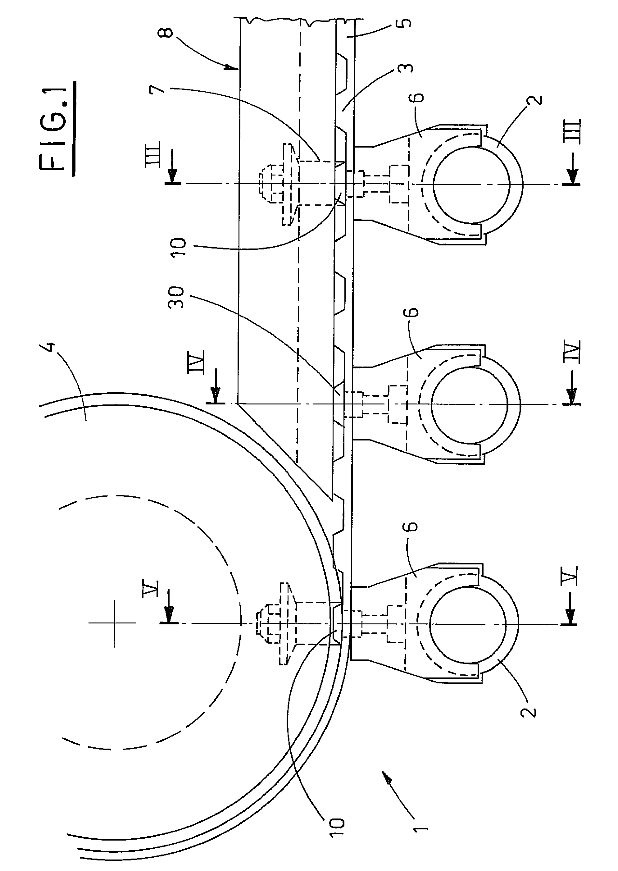
[0018]The device 1 is installed on a fixed structure not illustrated in the appended drawings. The fixed structure rotatably supports at least a pair of cogged wheels 4, which lie in the same horizontal plane and are keyed to respective vertical shafts. The cogged wheels 4 are turned in a known way.

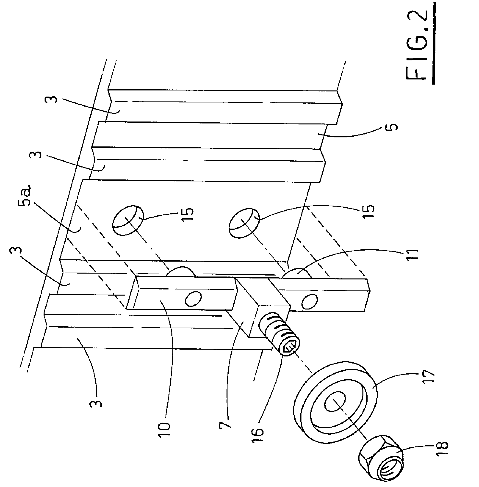
[0019]A cogged belt 5 wound on the cogged wheels 4 is provided on an internal surface thereof with a series of cogs 3 having a straight profile matching that of the cogs of the cogged wheels 4. The cogged belt 5 is translated in a horizontal plane, drawn by the cogged wheels 4.

[0020]A plurality of regularly distanced support means 6, which receive respective containers 2 to be transported, are constrained to the external surface of the cogged belt. In a known way, the support means 6 are constituted by a shaped portion which forms a horizontal support plane 6a for the container 2, and by a pair of appendages 6b which laterally surround the container and block it in the transport position....


PUM


Abstract

The device for transporting containers comprises a cogged belt which extends along a ring-wound trajectory and is wound on at least a pair of cogged wheels which are rotatable on vertical axes, and a plurality of regularly distanced support means borne on the external surface of the cogged belt, which receive respective containers. The cogged belt bears a plurality of skates constrained to the internal surface thereof which engage with guide means that are solidly restrained to a fixed structure of the device, in order to constitute a lateral constraint which prevents transversal movements and deformation of the cogged belt.

Description

BACKGROUND OF THE INVENTION[0001]This invention concerns a cogged belt device for in-line transport of containers, in particular, vials, rigid tubes and the like.[0002]In-line transport systems for containers, in particular, vials and the like, are known at present which are destined for use in automatic machines for filling and packing such containers. Transport systems of this type substantially comprise a pair of vertical-axis cogged wheels on which a cogged belt is wound which can translate in a horizontal direction, drawn by the cogged wheels. The cogged belt conveys a plurality of containers housed inside respective support means which are constrained to the cogged belt at regularly distanced positions.[0003]In particular, in a known technical solution, the support means exhibit a shaped portion which forms a horizontal support plane for the container, and a pair of appendages which laterally surround the container, thus retaining the container in a transport position. The sha...

Claims


Application Information

Patent Timeline
Patent Type & Authority Patents(United States)
IPC IPC(8): B65G17/12
CPCB65G17/12B65G47/841
Inventor MONTI, GIUSEPPE
Owner MARCHESINI GROUP SPA
Why Eureka
Try Eureka