
Frequency-division multiplexing transceiver apparatus, wave-number-division multiplexing transceiver apparatus and method

a transceiver and frequency division technology, applied in the field of frequency wave-numberdivision multiplexing transceiver apparatus and method thereof, can solve the problem of large papr tensor, and achieve the effect of reducing multi-path interferen

Inactive Publication Date: 2010-03-23
FUJITSU LTD
View PDF2 Cites 8 Cited by
  • Summary
  • Abstract
  • Description
  • Claims
  • Application Information

AI Technical Summary

Benefits of technology

[0015]The object of the present invention is to reduce multi-path interference without using a multi-path canceller.
[0016]In OFDM, there is a tendency for PAPR to become large due to multiplexing. Therefore, another object of the present invention is to prevent that PAPR from becoming large.
[0027]With this invention, it is possible to perform transmission using a pseudo-like OFDM method without using a multi-path canceller, so it is possible to reduce multi-path interference (MPI) the same as in the OFDM method, thus resulting in a frequency diversity effect.
[0028]Moreover, with this invention, symbol is transmitted in orthogonal frequencies or wave numbers, so spread gain is obtained, and it is possible to reduce PAPR.

Problems solved by technology

In OFDM, there is a tendency for PAPR to become large due to multiplexing.

Method used


Image

  • Frequency-division multiplexing transceiver apparatus, wave-number-division multiplexing transceiver apparatus and method
  • Frequency-division multiplexing transceiver apparatus, wave-number-division multiplexing transceiver apparatus and method
  • Frequency-division multiplexing transceiver apparatus, wave-number-division multiplexing transceiver apparatus and method

Examples


first embodiment

(A) First Embodiment

(a) Frequency-Division Multiplexing Transmission Apparatus

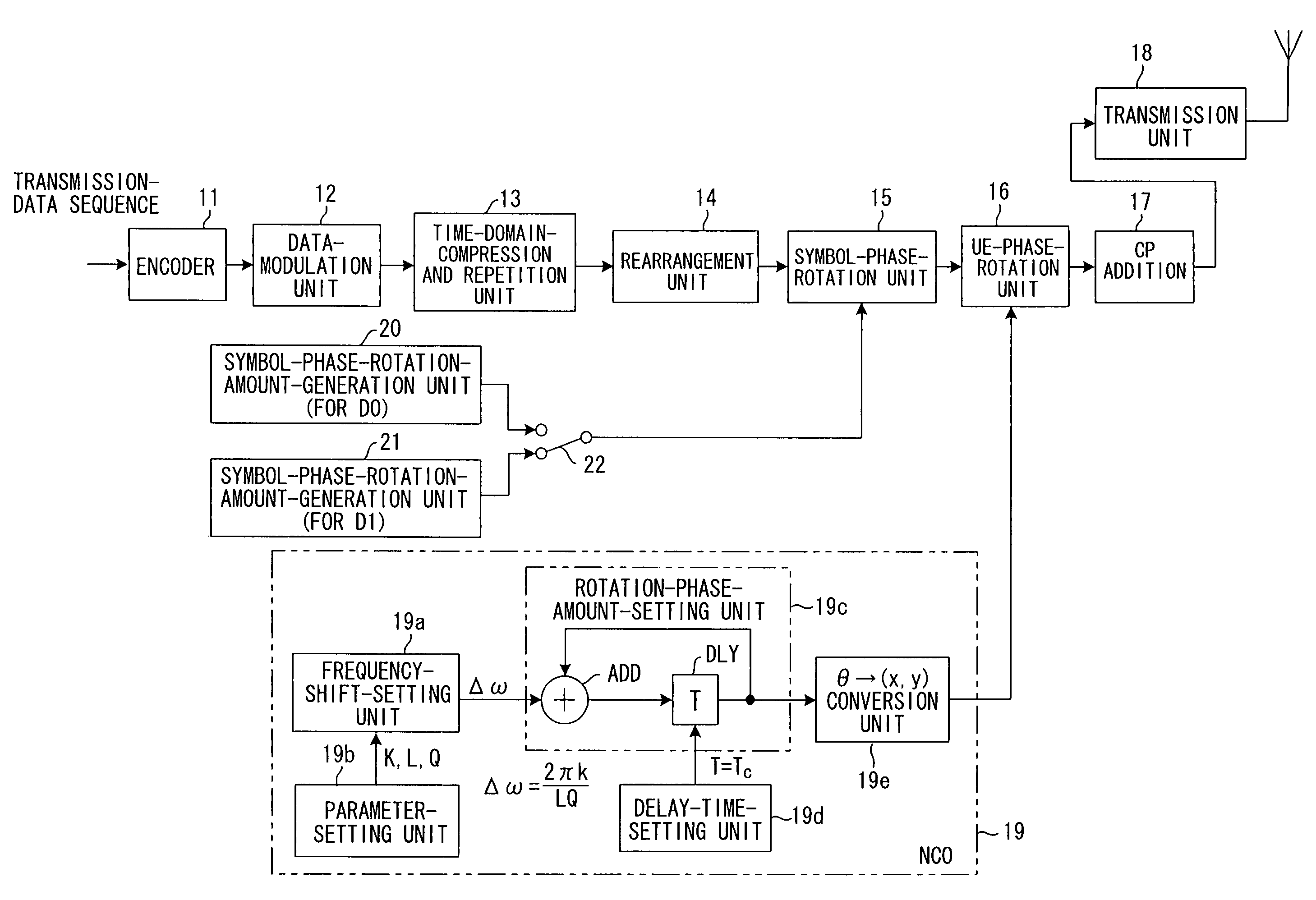
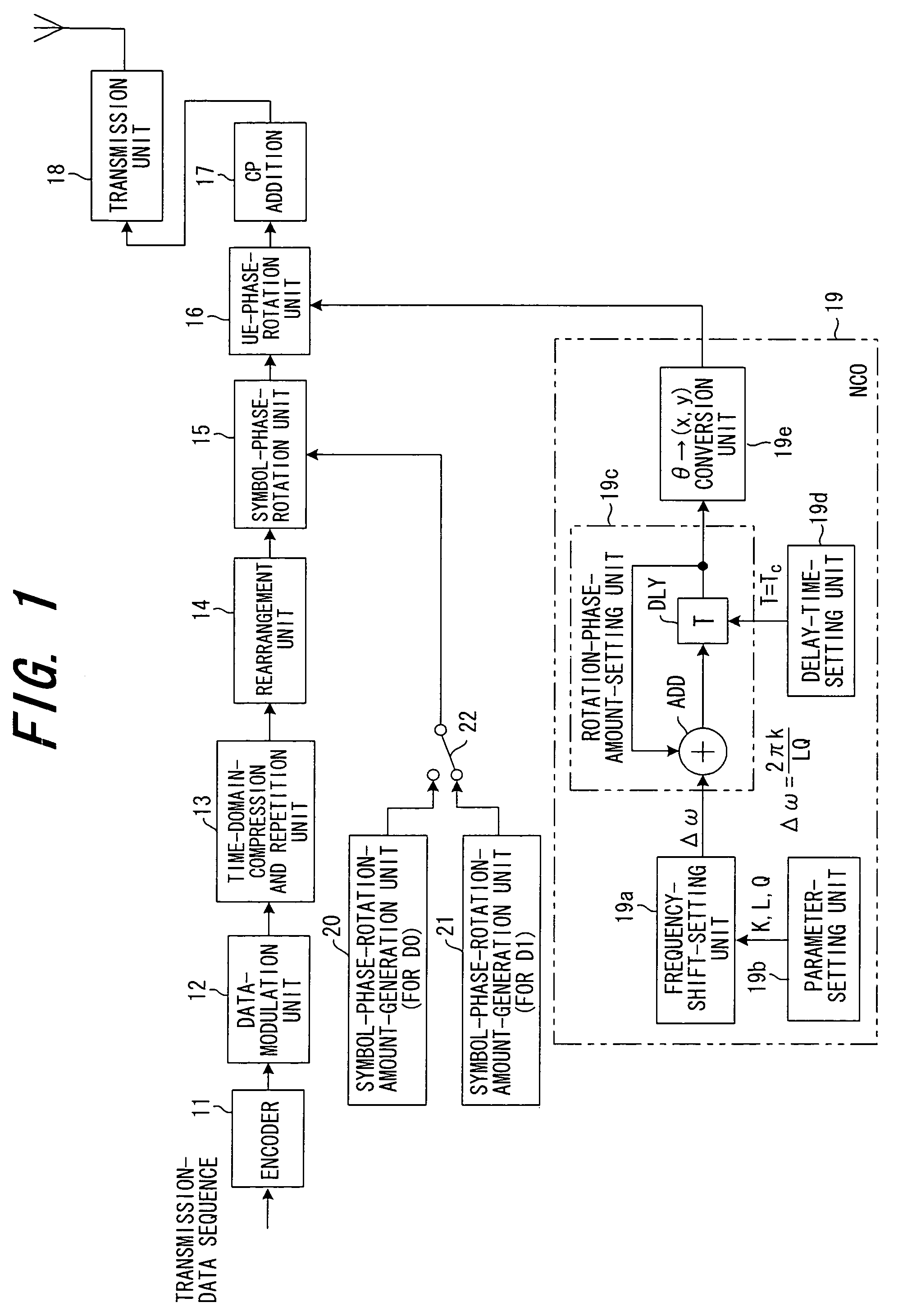
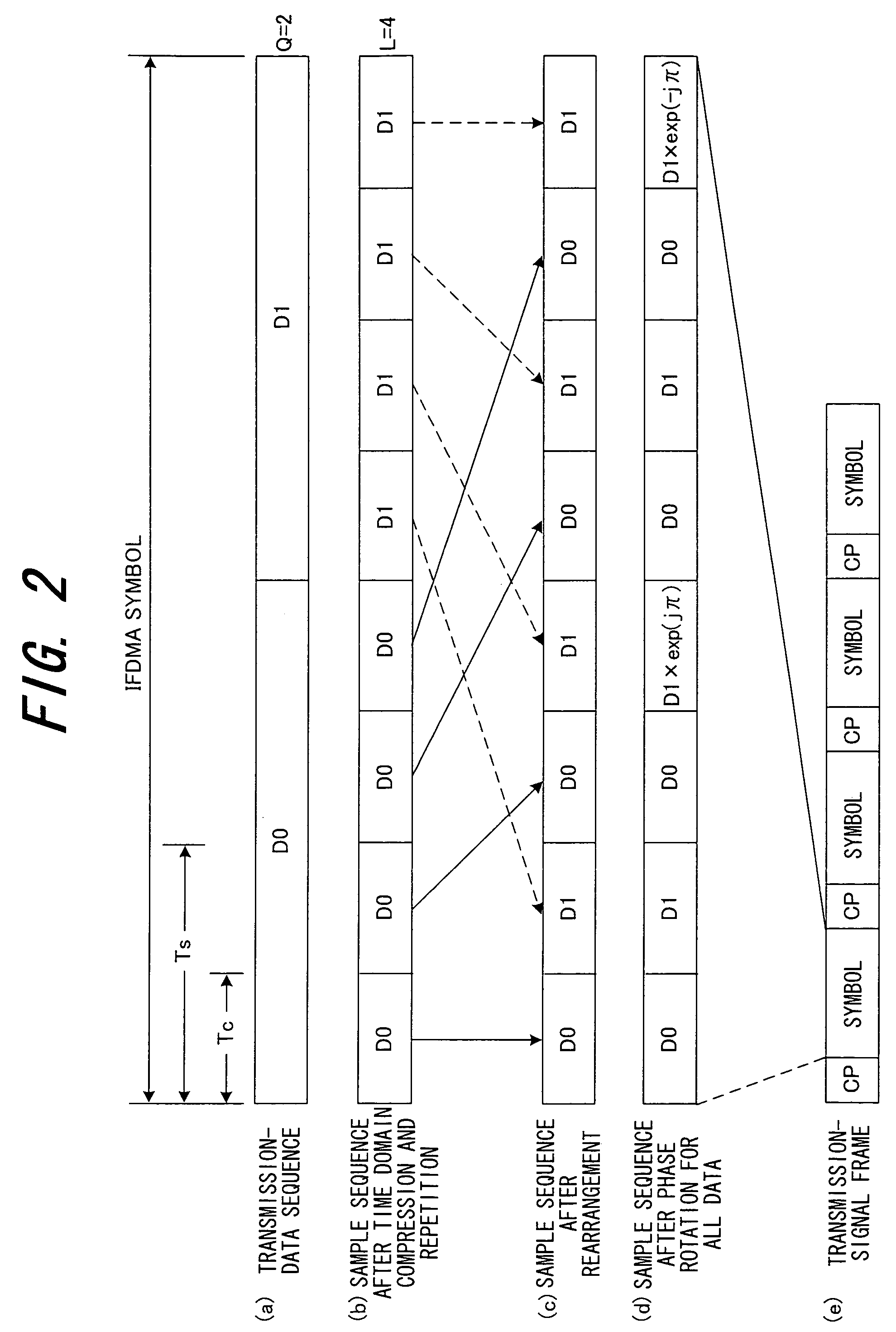
[0053]FIG. 1 is a block diagram showing a frequency-division multiplexing transmission apparatus of a first embodiment of the invention. FIG. 2 is a timing chart for explaining the operation of the frequency-division multiplexing transmission apparatus shown in FIG. 1. The frequency-division multiplexing transmission apparatus of this first embodiment can be used as a mobile station.

[0054]An encoder 11 performs channel encoding by applying error-correction encoding such as turbo encoding, or convolutional encoding to the input binary information sequence, and a data-modulation unit 12 converts the channel-encoded data sequence to I, Q complex components (symbols) in QPSK, for example. As shown in (a) of FIG. 2, one IFDMA symbol is composed of Q-number of symbols D0, D1 (Q=2 in the figure).

[0055]A time-domain compression and repetition unit 13 compresses the time domains of the two symbols D0, D1 of the IFD...

second embodiment

(B) Second Embodiment

[0082]FIG. 9 is a block diagram of a frequency-division multiplexing transmission apparatus of a second embodiment, and the same reference numbers are assigned to parts that are identical with those of the first embodiment shown in FIG. 1. The difference between FIGS. 1 and 9 is that the phase-rotation units 15 and 16 in FIG. 1 are combined to be a single phase-rotation unit 25 in FIG. 25.

[0083]An encoder 11 performs channel encoding by applying error-correction encoding such as turbo encoding, or convolutional encoding to the input binary information sequence, and a data-modulation unit 12 converts the channel-encoded data sequence to I, Q complex components (symbols) in QPSK, for example. As shown in (a) of FIG. 2, one IFDMA symbol is composed of Q-number of symbols D0, D1 (Q=2 in the figure).

[0084]A time-domain compression and repetition unit 13 compresses the time domains of the two symbols D0, D1 of the IFDMA symbol, then repeats each symbol L times (L=4 in...

third embodiment

(C) Third Embodiment

(a) Wave-Number-Division Multiplexing Transmission Apparatus

[0089]FIG. 10 is a block diagram of a wave-number-division multiplexing transmission apparatus of a third embodiment of the invention that transmits data by a wave-number spectrum, and FIG. 11 is a timing chart for explaining the operation of the wave-number-division multiplexing transmission apparatus shown in FIG. 10. The wave-number-division multiplexing transmission apparatus of this third embodiment can be used as a mobile station.

[0090]An encoder 51 performs channel encoding by applying error-correction encoding such as turbo encoding, or convolutional encoding to the input binary information sequence, and a data-modulation unit 52 converts the channel-encoded data sequence to I, Q complex components (symbols) in QPSK, for example. As shown in (a) of FIG. 11, one IWDMA symbol is composed of Q-number of symbols D0, D1 (Q=2 in the figure).

[0091]A time-domain compression and repetition unit 53 compres...


PUM


Abstract

A frequency-division multiplexing transmission apparatus for transmitting data in a frequency spectrum specific to both symbol and mobile station, is disclosed. The apparatus encodes transmission data, modulates the encoded data, compresses the time domains of each symbol of the modulated transmission-symbol sequence, repeats the symbols a specified number of times, rearranges each of the symbols of the obtained repetitive-symbol sequence so that they have the same arrangement as the transmission-symbol sequence, generates each phase that changes at a speed specific to each symbol of the transmission-symbol sequence, performs phase rotation specific to the symbols for each symbol of the rearranged repetitive-symbol sequence, generates phase that changes at a speed specific to a mobile station, performs phase rotation specific to the mobile station for the symbol sequence for which the phase rotation was performed, and transmits the phase-rotated symbol sequence.

Description

BACKGROUND OF THE INVENTION[0001]This invention relates to a frequency-division multiplexing transceiver apparatus, wave-number-division multiplexing transceiver apparatus and method thereof, and more particularly to a frequency-division multiplexing transceiver apparatus, wave-number-division multiplexing transceiver apparatus and method for transmitting data in a frequency spectrum or wave-number spectrum.[0002]DS-CDMA (Direct Sequence-Code Division Multiple Access) multiplies a narrow-band transmission signal by a spreading code in order to spread and transmit that transmission signal over a wider band. In DS-CDMA, when each of a plurality of mobile stations sends a transmission signal upon multiplying it by a spreading code having a certain spreading factor SF, the information transmission speed becomes 1 / SF. Therefore, in order to achieve a frequency utilization efficiency that is equivalent to that of TDMA, it is necessary in DS-CDMA to accommodate a number of signals that is ...

Claims


Application Information

Patent Timeline
Patent Type & Authority Patents(United States)
IPC IPC(8): H04B1/00H04B1/707H04B1/7097H04B7/26H04J1/00H04J11/00H04L27/01H04W72/04
CPCH04B1/707H04L5/0037H04L5/0044H04L27/2626H04J13/0048H04L5/0003H04L5/0007H04L27/2607
Inventor KAWASAKI, TOSHIO
Owner FUJITSU LTD
Learn More