Magnetic resonance imaging apparatus and magnetic resonance imaging apparatus control method

a magnetic resonance imaging and control method technology, applied in the direction of instruments, diagnostic recording/measuring, applications, etc., can solve problems such as deterioration in coronary artery visualization performan

Active Publication Date: 2010-03-23
TOSHIBA MEDICAL SYST CORP
View PDF9 Cites 3 Cited by
  • Summary
  • Abstract
  • Description
  • Claims
  • Application Information

AI Technical Summary

Problems solved by technology

In conventional MRCA, however, even if an optimal delay time (that allows imaging immediately before the detection of the next R wave) is set at the start of imaging, since the heart rate (R-R) of a patient changes, the set condition deviates from the optical condition in actual data acquisition, resulting in a deterioration in coronary artery visualization performance.

Method used


Image

  • Magnetic resonance imaging apparatus and magnetic resonance imaging apparatus control method
  • Magnetic resonance imaging apparatus and magnetic resonance imaging apparatus control method
  • Magnetic resonance imaging apparatus and magnetic resonance imaging apparatus control method

Examples


first embodiment

[0025]FIG. 1 is a block diagram showing the arrangement of a magnetic resonance imaging apparatus 10 according to this embodiment. The arrangement of the magnetic resonance imaging apparatus 10 will be described first with reference to FIG. 1.

[0026]The magnetic resonance imaging apparatus 10 comprises a static field magnet 11, a gradient field coil 13, a whole-body radio frequency (RF) coil 14, a radio frequency reception coil 15, a gradient field coil driving device 17, a whole-body RF coil driving device 18, an RF reception unit 19, a controller 20, a computing device 21, a display unit 23, an input unit 24, a storage unit 25, an ECG waveform acquiring device 31 housed in an ECG device 30, and an R wave time detection / storage device 32.

[0027]The static field magnet 11 is a magnet which generates a static field. The static field magnet 11 generates a homogenous static field. For example, as the static field magnet 11, a permanent magnet, superconductive magnet, or the like is used,...

second embodiment

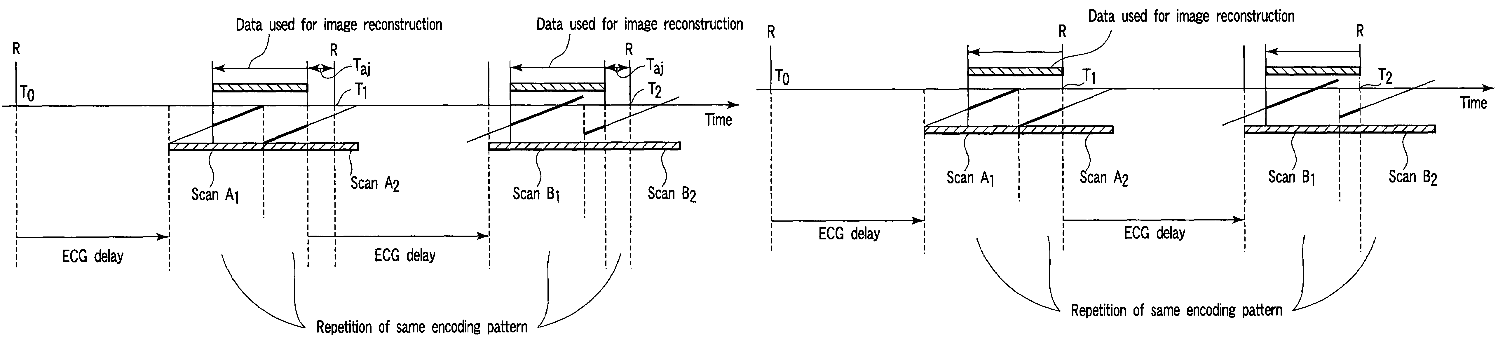
[0067]The second embodiment of the present invention will be described next. This embodiment does not use any ECG delay unlike the first embodiment and is directed to perform imaging based on the above retrospective function by executing continuous scans.

[0068]FIG. 5 is a view for explaining a full-retrospective imaging function according to the second embodiment and a view showing the relationship between the R wave occurrence times and the scan timings.

[0069]First of all, the (almost) average R-R time of a patient is obtained, and an interval longer than the obtained time by a predetermined period of time is set as a reference interval. As shown in FIG. 5, in this reference interval, data acquisition is performed by repeatedly and continuously executing a scan in accordance with the same encoding pattern. The MR data corresponding to the respective phase encoding patterns which are acquired in this manner are sequentially stored in a storage unit 25 in association with the respect...

third embodiment

[0074]The third embodiment of the present invention will be described next. In this embodiment, the adjustment interval Taj described in the first and second embodiments is actively controlled in accordance with a request from the user.

[0075]A technique of determining the adjustment interval Taj determines the range of data to be extracted for reconstruction. For this reason, the value of the adjustment interval Taj must be so determined as to include a cardiac time phase necessary for image diagnosis. In general, the time phases in which the cardiac motion stops during one heartbeat of a person include systole and end-diastole. If, therefore, the operator is interested in end-diastole in image diagnosis, the value of the adjustment interval Taj and an ECG delay time after an R wave occurring need to be determined such that extracted data includes data concerning the end-diastole time phase.

[0076]In this embodiment, in order to determine the value of the adjustment interval Taj so a...


PUM


Abstract

Data acquisition based on the same MRI encoding pattern is repeated at least once for each R wave occurring at time T0 used as a trigger. The necessary number of data for image reconstruction are extracted as subsets of a complete MRI data set from the resulting plural sets of acquired MRI by temporally retrospecting from the next R wave occurrence time (time T1) after the R wave (time T0) used as the trigger. The extracted data subsets are then rearranged to generate a complete composite MRI data set which is then used for image reconstruction of heart movement associated with end-diastole after the occurrence of the triggering R wave.

Description

BACKGROUND OF THE INVENTION[0001]1. Field of the Invention[0002]The present invention relates to an imaging technique for a magnetic resonance imaging apparatus and, more particularly, to a technique used for imaging a coronary artery.[0003]2. Description of the Related Art[0004]A magnetic resonance imaging apparatus is an apparatus which images the chemical and physical microscopic information of a substance or is used for the observation of a chemical shift spectrum by using a phenomenon in which when a group of nuclei having a unique magnetic moment is placed in a homogenous static field, they resonantly absorb energy of an RF field that rotates at a specific frequency.[0005]Recently, in image diagnosis using this magnetic resonance imaging apparatus, magnetic resonance coronary angiography (MRCA) using an imaging method (TrueSSFP / FISP / Balanced FFE method or the like) which uses a steady state has been frequently used. This method can visualize a coronary artery without using any...

Claims


Application Information

Patent Timeline
Patent Type & Authority Patents(United States)
IPC IPC(8): A61B5/05
CPCG01R33/5673
Inventor KUHARA, SHIGEHIDEYUI, MASAOKASSAI, YOSHIMORI
Owner TOSHIBA MEDICAL SYST CORP
Why Eureka
Try Eureka