System for detecting and transmitting test data from a pressure chamber filled with a high-pressure fluid

Active Publication Date: 2010-03-23
PARKER INTANGIBLES LLC
View PDF24 Cites 0 Cited by
  • Summary
  • Abstract
  • Description
  • Claims
  • Application Information

AI Technical Summary

Benefits of technology

[0003]The object of the present invention is therefore to provide a system for detecting and transmitting test data from a pressure chamber fil

Problems solved by technology

In the field of hydraulic valves, for example, there is frequently the problem of detecting the movement of a movable valve piston in the enclosure filled with a high-pressure fluid using a position measuring system.
This is associated with the disadvantage that the sealing of th

Method used


Image

  • System for detecting and transmitting test data from a pressure chamber filled with a high-pressure fluid
  • System for detecting and transmitting test data from a pressure chamber filled with a high-pressure fluid
  • System for detecting and transmitting test data from a pressure chamber filled with a high-pressure fluid

Examples


Example

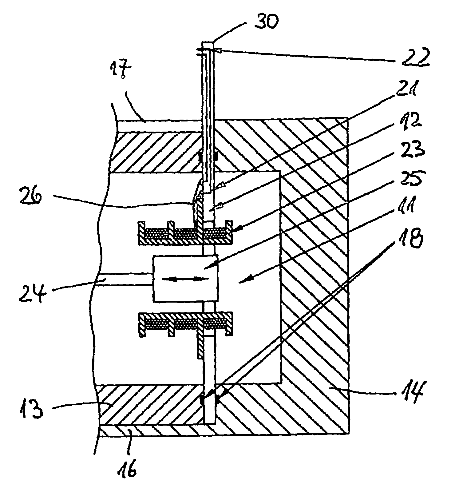
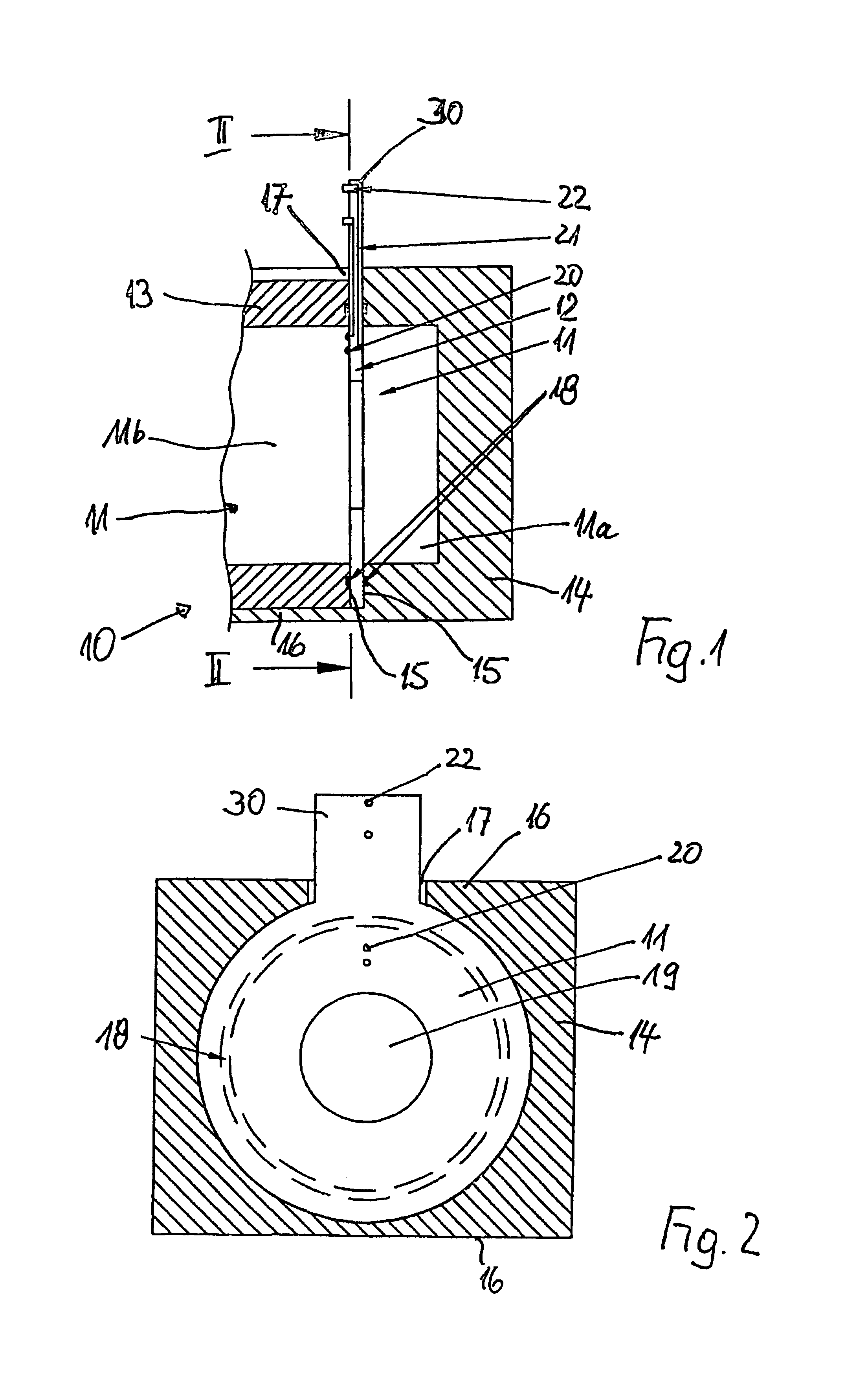
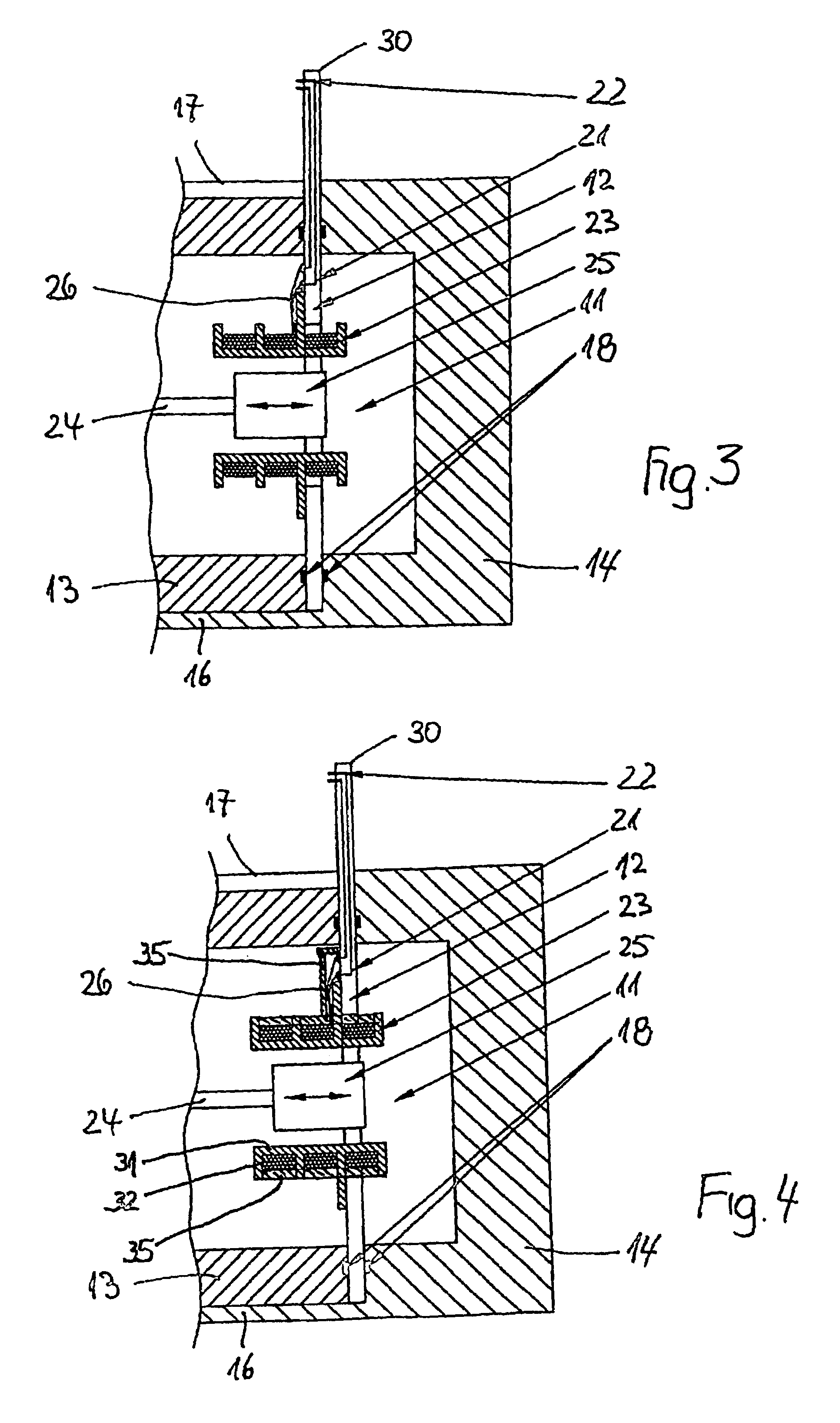
[0024]Housing 10 shown in partial section in FIG. 1 encloses a pressure chamber 11 in which a circuit board 12 is situated in such a way that sub-chambers 11a, 11b of pressure chamber 11 are located on both sides of circuit board 12. In the plane of the arrangement of circuit board 12, housing 10 is separated into one housing half 13 and one housing half 14, the faces 15 of which are adjacent to one another and clamp circuit board 12 between them. A flange 16 projecting axially from housing half 14 encompasses the outer circumference of housing half 13.

[0025]As a combined view of FIGS. 1 and 2 shows, flange 16 of housing half 14 is designed to have a cutout 17 through which a projection 30 located on circuit board 12 is guided out of the housing and projects above the outer circumference of the housing.

[0026]In order to seal the clamping of the circuit board, seals 18 in the form of O-rings are situated between faces 15 of housing halves 13 and 14 which clamp the circuit board 12 an...


PUM


Abstract

The invention relates to an arrangement for detecting and transmitting test data from a housing (10) including a pressure chamber (11) that is filled with a high-pressure fluid and is homogeneously pressurized via strip conductors (21) which are connected to a sensor (23) and are guided out of the housing (10). A circuit board (12), both faces of which are subjected to the pressure prevailing in the pressure chamber (11) and at least one portion (30) of which extends out of the housing is disposed inside the pressure chamber (11) as a support of the strip conductors (21). The housing (10) that encloses the pressure chamber (11) is separated on the plane of the printed board (12), the faces of the housing halves (13, 14) clamping the printed board (12) in such a way that radial forces exercised within the printed board when pressure is applied are absorbed by the housing.

Description

TECHNICAL FIELD[0001]The present invention relates to a system for detecting and transmitting test data from a housing having a pressure chamber that is filled with a high-pressure fluid and is homogeneously pressurized.BACKGROUND OF THE INVENTION[0002]In the field of hydraulic valves, for example, there is frequently the problem of detecting the movement of a movable valve piston in the enclosure filled with a high-pressure fluid using a position measuring system. In the context of known systems, for example, a push rod attached to the valve piston is guided out of the housing and is coupled to a position measuring system, for example in the form of an LVDT system, situated outside of the housing. This is associated with the disadvantage that the sealing of the push rod leading out of the pressure chamber is complex and can also represent a weak point over the life of the valve. Another disadvantage is that the additional placement of a position measuring system outside of the hous...

Claims


Application Information

Patent Timeline
IPC IPC(8): G06F17/40F15B13/04F17C13/02G01D11/24
CPCF15B13/0402F17C13/025G01D11/245F15B2013/0409G08C19/00
Inventor SCHEFFEL, GERD
Owner PARKER INTANGIBLES LLC
Why Eureka
Try Eureka