Heating and air conditioning service gauge

a technology for heating and air conditioning and service gauges, applied in heating types, instruments, lighting and heating apparatuses, etc., can solve the problems of inconvenient use of lookup charts, time-consuming, error-prone, etc., and achieve the effect of clear understanding

Active Publication Date: 2010-03-30
DIVERSITECH
View PDF11 Cites 11 Cited by
  • Summary
  • Abstract
  • Description
  • Claims
  • Application Information

AI Technical Summary

Benefits of technology

[0008]The pressure gauge of the present invention further includes a sensor that measures changes in refrigerant pressure and produces an electronic pressure signal that is proportional to the measured refrigerant pressure. A battery powered microprocessor within the gauge receives the electronic pressure signal, converts the electronic pressure signal to a refrigerant pressure value in PSI or KPa, and digitally displays the refrigerant pressure value on the face of the gauge. In addition, the microprocessor can convert the refrigerant pressure value to a refrigerant saturated vapor equivalent temperature va...

Problems solved by technology

Because HVAC systems respond very slowly and because the pressure and the saturated vapor equivalent temperature must be ...

Method used


Image

  • Heating and air conditioning service gauge
  • Heating and air conditioning service gauge
  • Heating and air conditioning service gauge

Examples


first embodiment

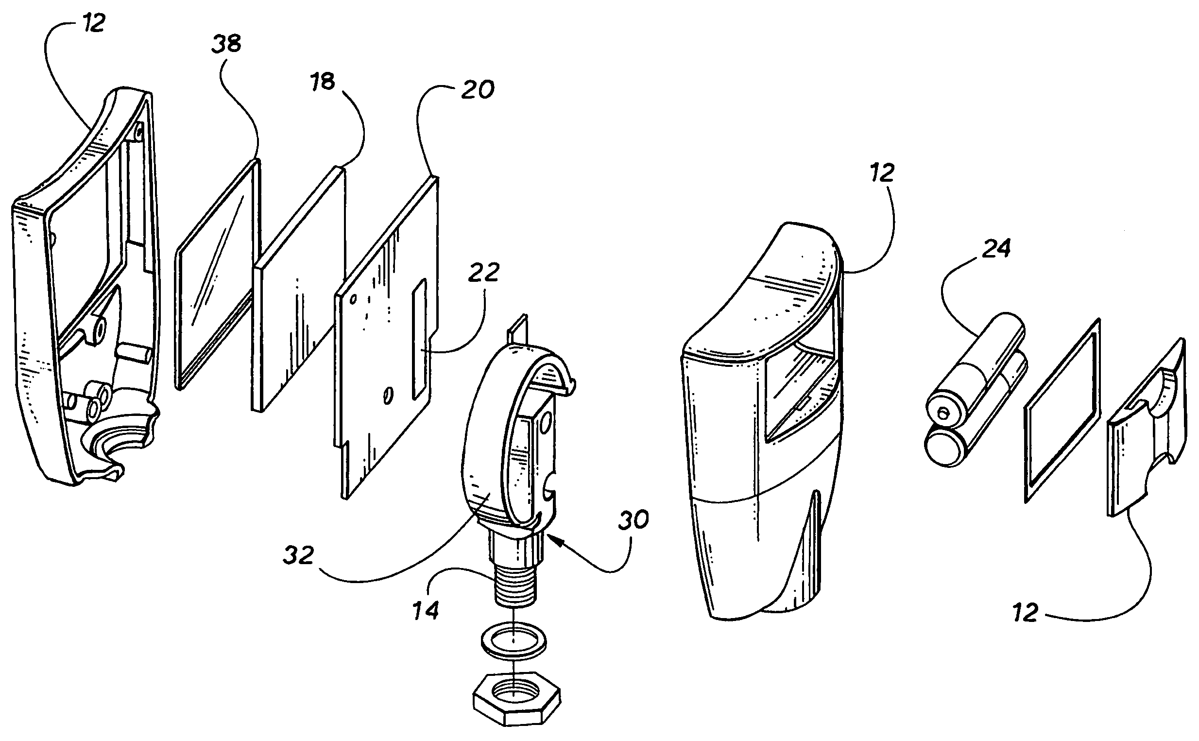
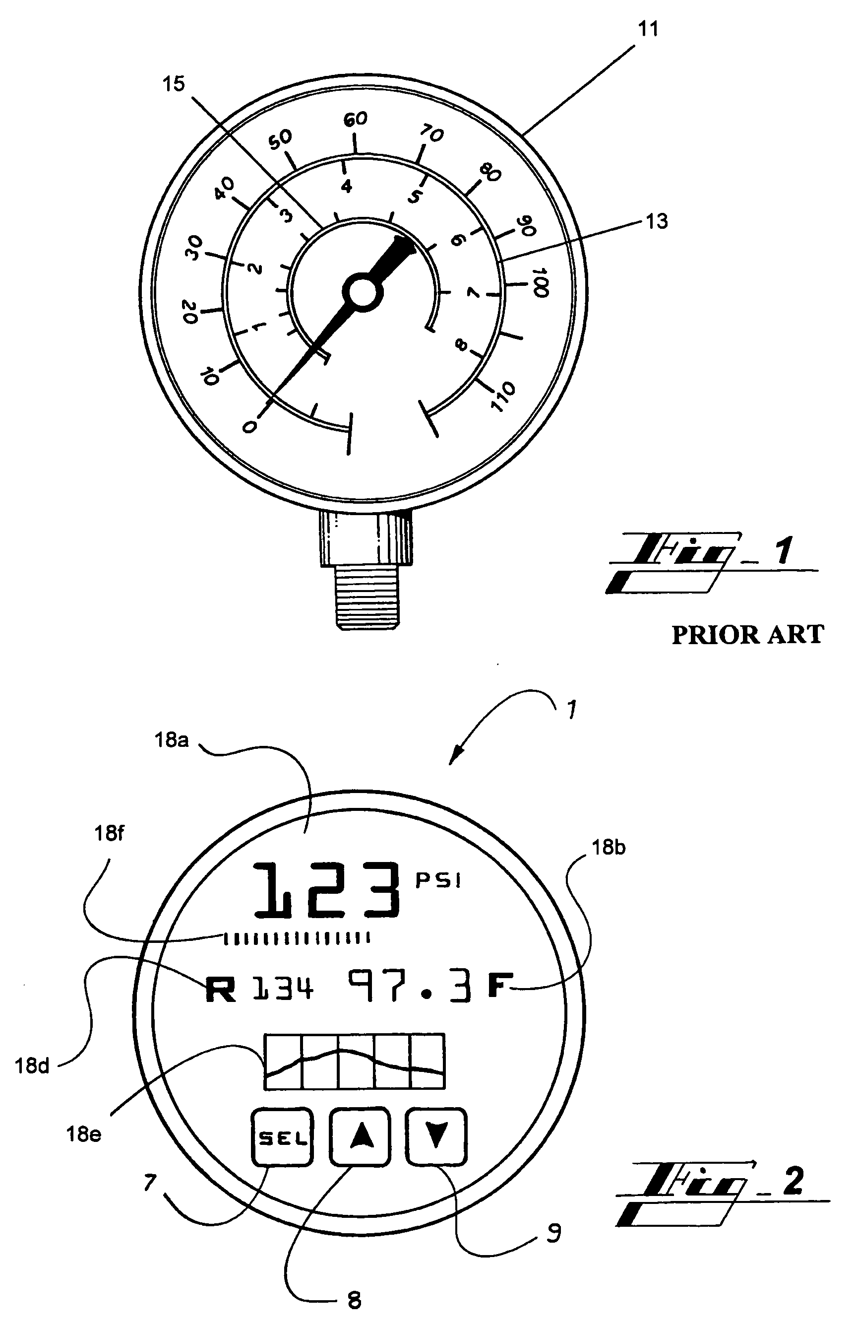
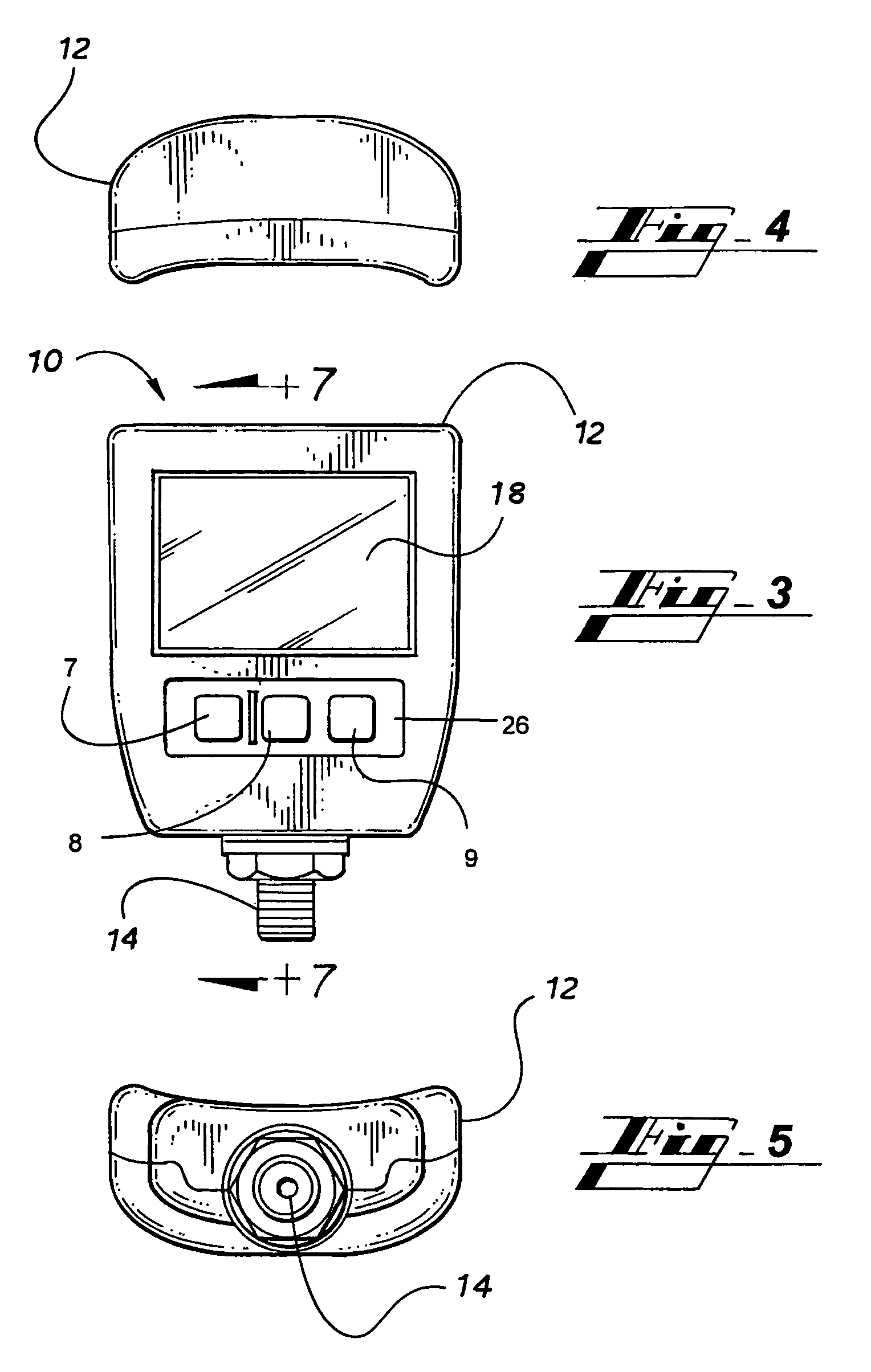
[0028]FIGS. 3-8 show a first embodiment of the present invention. FIG. 2 shows a second embodiment of the present invention. FIG. 15 shows a third embodiment of the present invention. FIGS. 9-14 show a pressure sensor that is common to all three embodiments of the present invention. FIG. 16 shows a functional block diagram that is common to all three embodiments of the present invention, except for the additional expert functions that are part of the present invention.

[0029]Turning to FIGS. 3-8, a digital pressure gauge 10 in accordance with a first embodiment of the present invention comprises a case 12, a pressure connector 14, a pressure manifold 16 (FIG. 7), a display 18 (with protective window 38), a microprocessor 22 (FIGS. 8 and 16), and a pressure sensor 30. The display 18 is an LED display that may display all of the functions of the pressure gauge 10 including without limit display functions 18a-g of FIG. 16.

[0030]With reference to FIGS. 3-8 and 16, the pressure sensor 30,...


PUM


Abstract

A pressure gauge for determining refrigerant pressure and the saturated vapor equivalent temperature for a refrigerant in an HVAC system. The pressure gauge employs a bourdon tube with at least one attached strain gauge to sense the refrigerant pressure and produce an electronic pressure signal. The electronic pressure signal from the output of the strain gauge is attached to a microprocessor, which calculates and displays the refrigerant pressure, the saturated vapor equivalent temperature for a variety of refrigerants, and produces instantaneous and time lapsed representations of those parameters.

Description

CLAIM OF PRIORITY[0001]This application is a continuation-in-part of U.S. patent application Ser. No. 11 / 743,374, filed May 2, 2007 now U.S. Pat. No. 7,437,941, which claims priority from U.S. Provisional Patent Application Ser. No. 60 / 746,720 filed on May 8, 2006, and this application claims priority from U.S. Provisional Patent Application Ser. No. 61 / 026,812 filed on Feb. 7, 2008, which are incorporated herein in their entirety.FIELD OF THE INVENTION[0002]This invention relates to a service gauge used for installing and servicing an HVAC system.BACKGROUND OF THE INVENTION[0003]In order to install or service an HVAC system, HVAC service personnel must measure the HVAC system refrigerant pressure and from the refrigerant pressure determine the saturated vapor equivalent temperature for the particular refrigerant used in the HVAC system being installed or serviced. Conventionally, the refrigerant pressure is measured with an analog pressure gauge and the saturated vapor equivalent t...

Claims


Application Information

Patent Timeline
IPC IPC(8): G01L9/00
CPCF24F11/001G01L9/0027F24F2011/0043F24F11/30F24F2110/00F24F2140/12F24F11/52F24F11/63
Inventor WARD, CHARLES BARRY
Owner DIVERSITECH
Why Eureka
Try Eureka