Zero-turn radius vehicle with steerable front wheels

a technology of steering wheel and zero-turn radius, which is applied in the direction of non-deflectable wheel steering, transportation and packaging, agriculture tools and machines, etc., can solve the problems of asynchronous steering system and inability to driv

Inactive Publication Date: 2010-03-30
GIZMOW
View PDF19 Cites 27 Cited by
  • Summary
  • Abstract
  • Description
  • Claims
  • Application Information

AI Technical Summary

Benefits of technology

[0013]In the front wheel steering system, the steering device is connected by one or more steering shafts to at least one wheel sprocket. Again, for the sake of convenience, a vehicle having two front wheels is described, and so the discussion involves a first and second wheel sprocket. This shall not be deemed to limit the invention to requiring two wheel sprockets. The first and second wheel sprockets are connected to the caster pivot mounts of the first and second steerable front wheels, respectively. Preferably the wheel sprockets are ellipsoidal, ovoidal, oblong, or of any similar regular or non-regular geometric shape having at least two rounded sides separated by a first axis and at least two sides separated by a second axis. In the preferred embodiment, the first axis (a major axis) is greater than the second axis (a minor axis). Sprockets having such design are termed, collectively, as being “oblongated”. Such specially designed sprockets are needed in order to provide proper turning of the steerable wheels, to ensure the steerable wheels rotate during the turn instead of drag across the turf, and to keep proper tension in the chains. This is possible because the oblongated sprockets provide an unmatched radius of rotation about the center of the drive wheel axis for one steerable front wheel with respect to the other steerable front wheel. This provides an asynchronously steered system and is not possible with standard circular sprockets. Rotating the steering wheel in turn rotates the steering shaft via one or more chains that meshingly engage the first and second wheel sprockets. The oblongated wheel sprockets rotate the first and second steerable front wheels in a manner that provides true zero-radius turning capability without ploughing or scraping the turf.
[0023]When the forward input is depressed, as stated, the linkage rotates the engagement cam shaft forward, which moves the first and second cam followers forward such that the first and second bearings are now in a receiving position. In this receiving position, if the user provides a steering input, the steering cam shaft rotates. If the steering input is a left turn, the first steering cam begins to rotate about its axis of rotation, and when it does it brings its increasing radius into contact with the first bearing. As more steering input is applied, more of the increasing radius of the first steering cam contacts the first bearing, forcing the first bearing and the first cam follower in an increasingly backward direction. Because the first cam follower is connected to the first end of the first push cable, the backward direction of the cam follower provides a compressive force (a “push”) onto the pump arm of the first pump associated with the first (inside) drive wheel. This has the effect of slowing the inside drive wheel in proportion to the left steering input.
[0024]In similar fashion, if the steering input is a right turn, the second steering cam begins to rotate about its axis of rotation, and when it does it brings its increasing radius into contact with the second bearing. As more steering input is applied, more of the increasing radius of the second steering cam contacts the second bearing, forcing the second bearing and the second cam follower in an increasingly backward direction. Because the second cam follower is connected to a first end of the second push cable, the backward direction of the cam follower provides a compressive force (a “push”) onto the pump arm of the second pump associated with the second (inside) drive wheel. This has the effect of slowing the inside drive wheel in proportion to the right steering input.
[0026]Optionally, the invention comprises an automatic self-catching seat latch for use with or without roll-over protection systems (“ROPS”). The increasing use of ROPS systems provides additional safety features for the operator of such vehicles. However, one requirement of ROPS systems is the inclusion of a positive seat latch mechanism that locks the seat to the frame. Many varieties of seat latch systems are found in the art, but a majority of these systems utilize components welded directly to a seat mount or to the frame. The welded structure creates at least two significant problems. First, if the welds break, the entire seat mount must be removed in order for the latch to be repaired or replaced. This costs the user significant dollars and significant time to repair. Second, because of the welded structure, no adjustability is designed into the latch. Therefore, upon lengthy use and normal wear and tear, the latch mechanisms may become less effective due to movement of the components over time. An optional adjustable removable seat latch system is provided in the preferred embodiment to eliminate these problems.
[0028]Optionally, the apparatus can also include a cruise control system to allow the user to remove his / her foot from the forward pedal, thereby reducing user fatigue during long mowing operations. The cruise control system comprises a cruise control shaft having a cruise control link operatively connected to a handle. The cruise control link connects to the forward control shaft that in turn connects to the pump forward control assembly. Thus, when the user moves the handle to engage the cruise control system, the cruise control shaft rotates the cruise control link into engagement with the forward control shaft, which moves the pump forward control assembly forward, moving the pump arms of the pumps forward in an equal amount. A catch is provided for the handle so that the user can select and maintain the desired amount of ground speed for the cruise control.

Problems solved by technology

This provides an asynchronously steered system and is not possible with standard circular sprockets.

Method used


Image

  • Zero-turn radius vehicle with steerable front wheels
  • Zero-turn radius vehicle with steerable front wheels
  • Zero-turn radius vehicle with steerable front wheels

Examples


Embodiment Construction

[0077]While the present invention will be described more fully hereinafter with reference to the accompanying drawings in which particular embodiments and methods are shown, it is to be understood from the outset that persons of ordinary skill in the art may modify the invention herein described while achieving the functions and results of this invention. Sound engineering judgment may be used to modify various aspects and components of the invention without detracting from the broad, general teachings hereof. Accordingly, the description that follows is to be understood as illustrative and exemplary of specific embodiments within the broad scope of the present invention and not as limiting the scope of the invention. In the following descriptions, like numbers refer to similar features or like elements throughout.

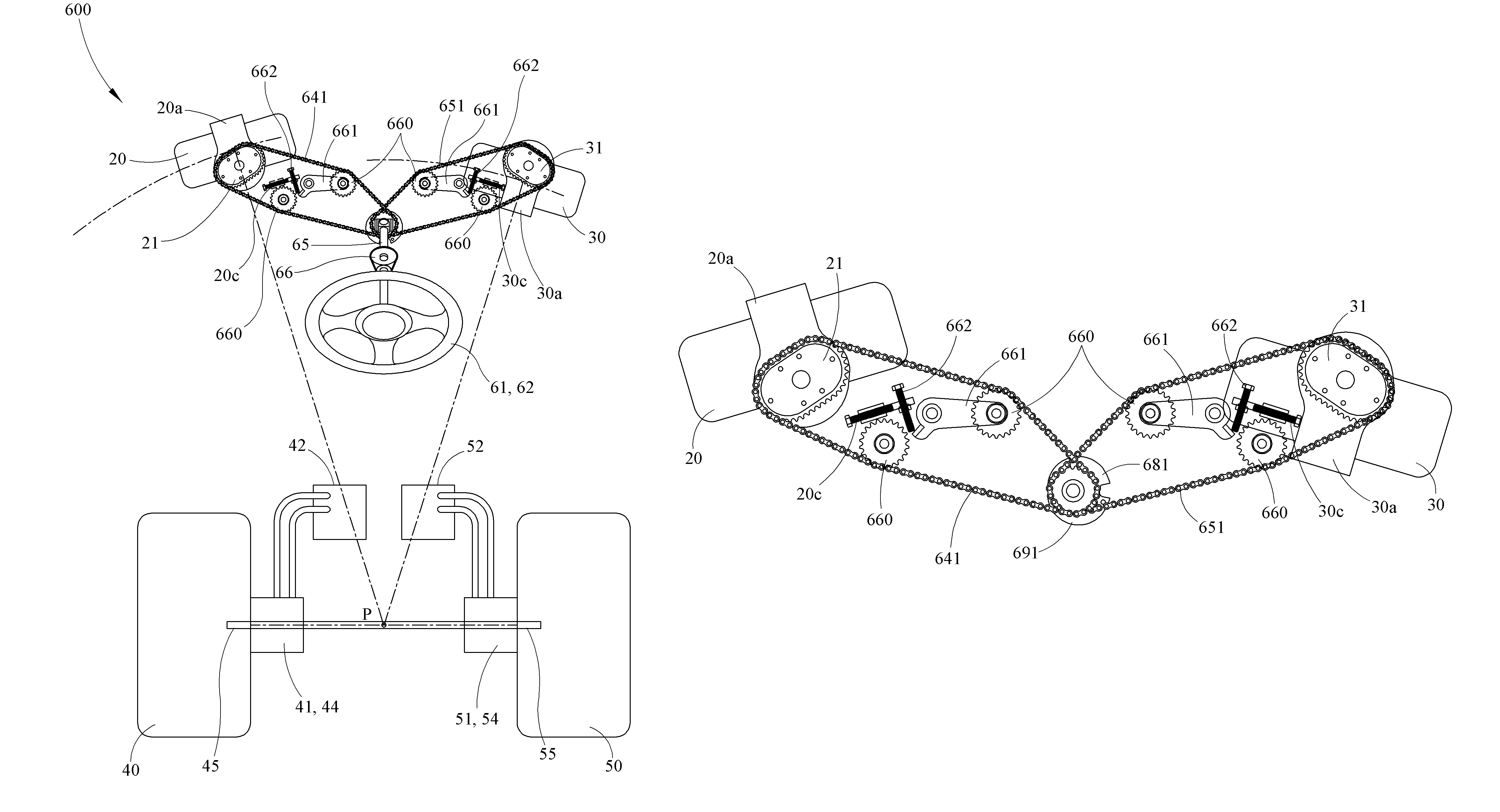
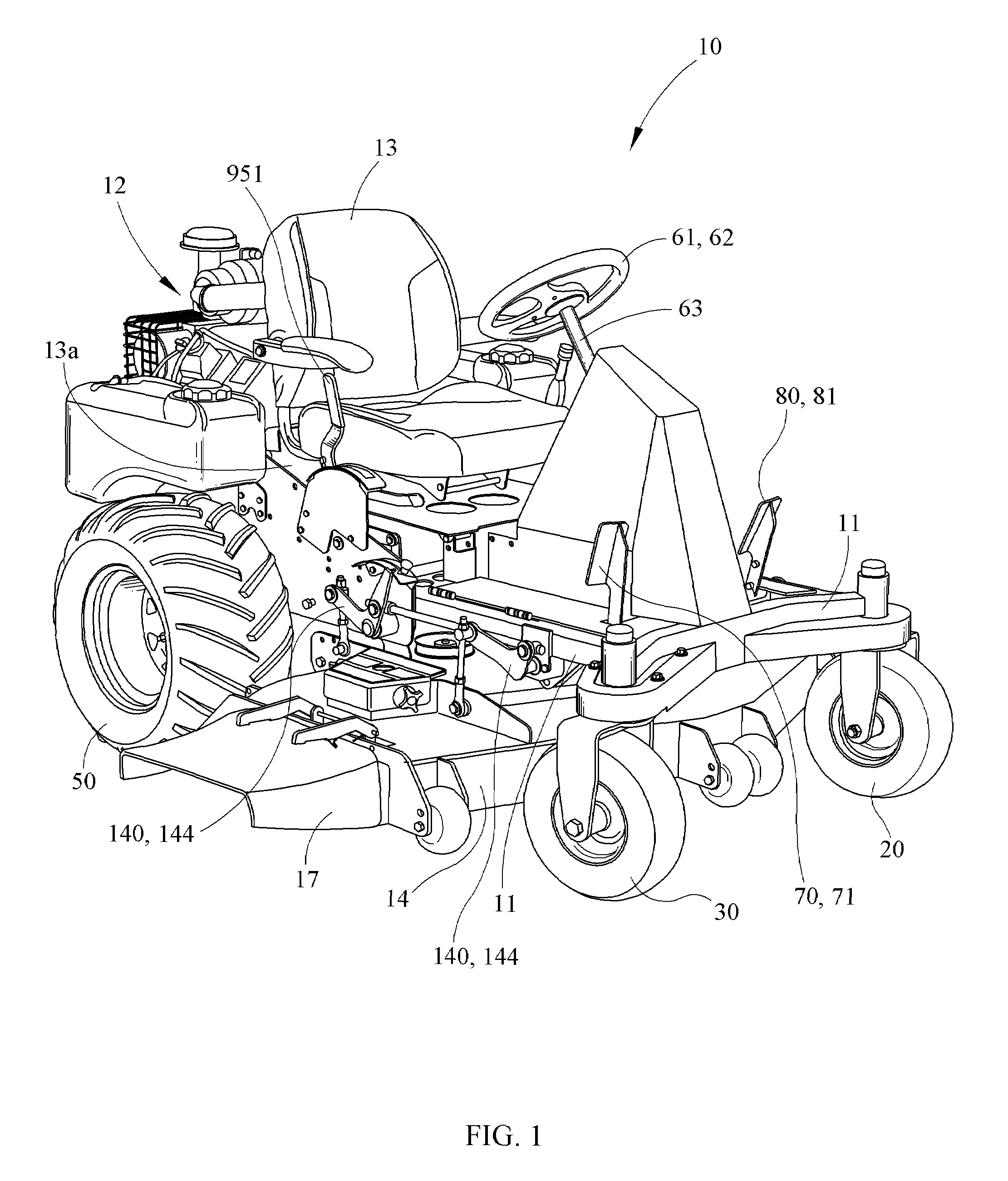
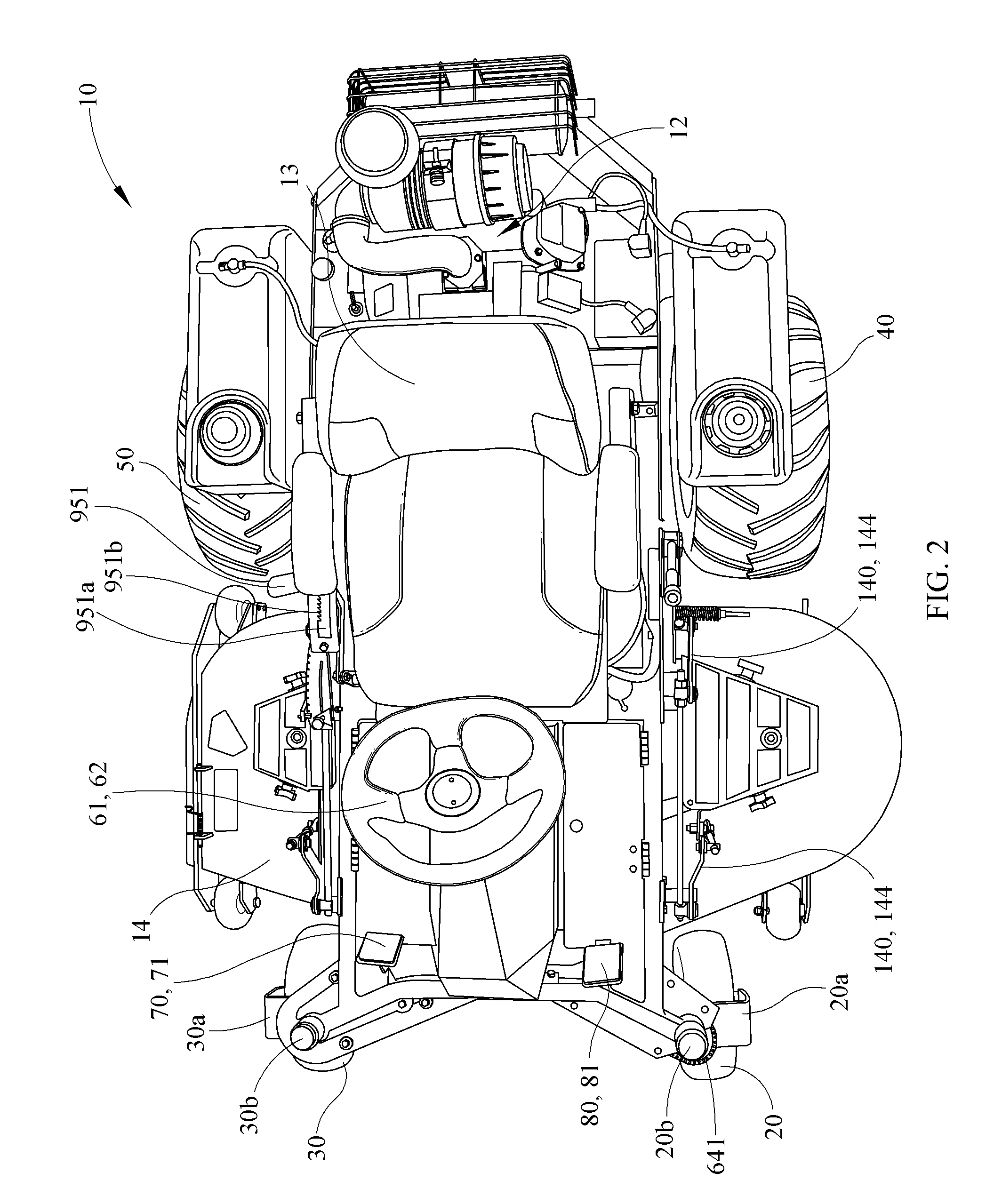
[0078]FIGS. 1 through 37 depict an apparatus 10 in the form of a vehicle according to one embodiment of the invention. Throughout this description the terms “apparatus” an...


PUM


Abstract

The present invention relates to a zero turning radius vehicle having at least one steerable front wheel and a multistage steering input system separately capable of steering the at least one front wheel and selectively driving the drive wheels. A front wheel steering system comprises at least one oblongated sprocket meshingly connected to a steering shaft. An engagement cam system provides the ability to selectively, independently couple the steering wheel to pump arms driving a first and second drive wheel. A steering cam shaft comprises at least one steering cam that acts on at least one bearing. Once the engagement cam system rotates the at least one bearing into place to receive the at least one steering cam, rotation of the steering cam independently alters the speed of one drive wheel in relation to the other drive wheel in response to steering input provided by the operator.

Description

CROSS REFERENCE TO RELATED APPLICATIONS[0001]This patent application is a continuation of, currently pending, U.S. patent application Ser. No. 10 / 968,758, entitled Zero-turn Radius Vehicle with Steerable Front Wheels”, filed on Oct. 15, 2004, which claims priority (under 35 USC §119(e)) to U.S. Provisional Application Ser. No. 60 / 511,529, filed on Oct. 15, 2003 titled “Zero-turn radius lawnmower with steerable front wheels.”BACKGROUND OF THE INVENTION[0002]1. Field of the Invention[0003]The present invention relates generally to a zero turning radius vehicle. Specifically, the present invention provides a zero turning radius vehicle with outboard steerable front wheels and independently-driven rear wheels.[0004]2. Background[0005]Whether a lawn mower is utilized commercially or for personal use, efficient operation is essential. In commercial settings, time is money and contractors desire to finish a yard as quickly as possible so they may complete more jobs in a day. Similarly, a h...

Claims


Application Information

Patent Timeline
Patent Type & Authority Patents(United States)
IPC IPC(8): B60K17/34B62D3/02
CPCB62D7/08B62D9/00B62D11/006B62D11/24
Inventor BLAND, MARK CHARLESHUNCILMAN, JEFFERY A.
Owner GIZMOW
Why Eureka
Try Eureka