
Operating table support clamp

a technology for supporting clamps and operating tables, which is applied to support devices, candle holders, and light support devices, etc., can solve the problems of prior art clamps not engaging the rail, devices that cannot be sterilized, and virtually impossible sterilization of devices, so as to prevent accidental rotation or loosening of the operating lever, and the versatility and adjustability of positioning accessories

Inactive Publication Date: 2010-03-30
DASILVA MANUEL F
View PDF40 Cites 29 Cited by
  • Summary
  • Abstract
  • Description
  • Claims
  • Application Information

AI Technical Summary

Benefits of technology

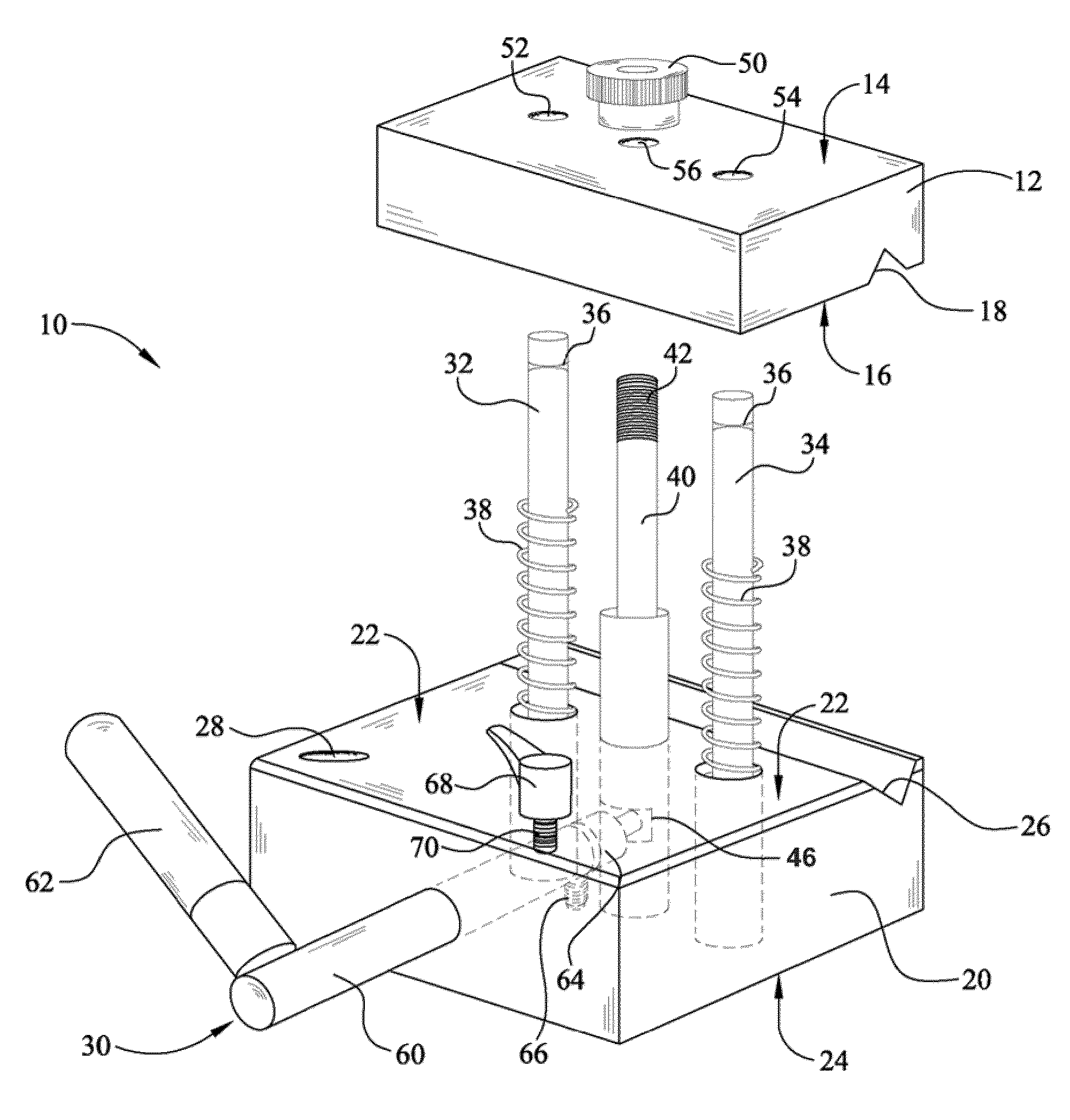
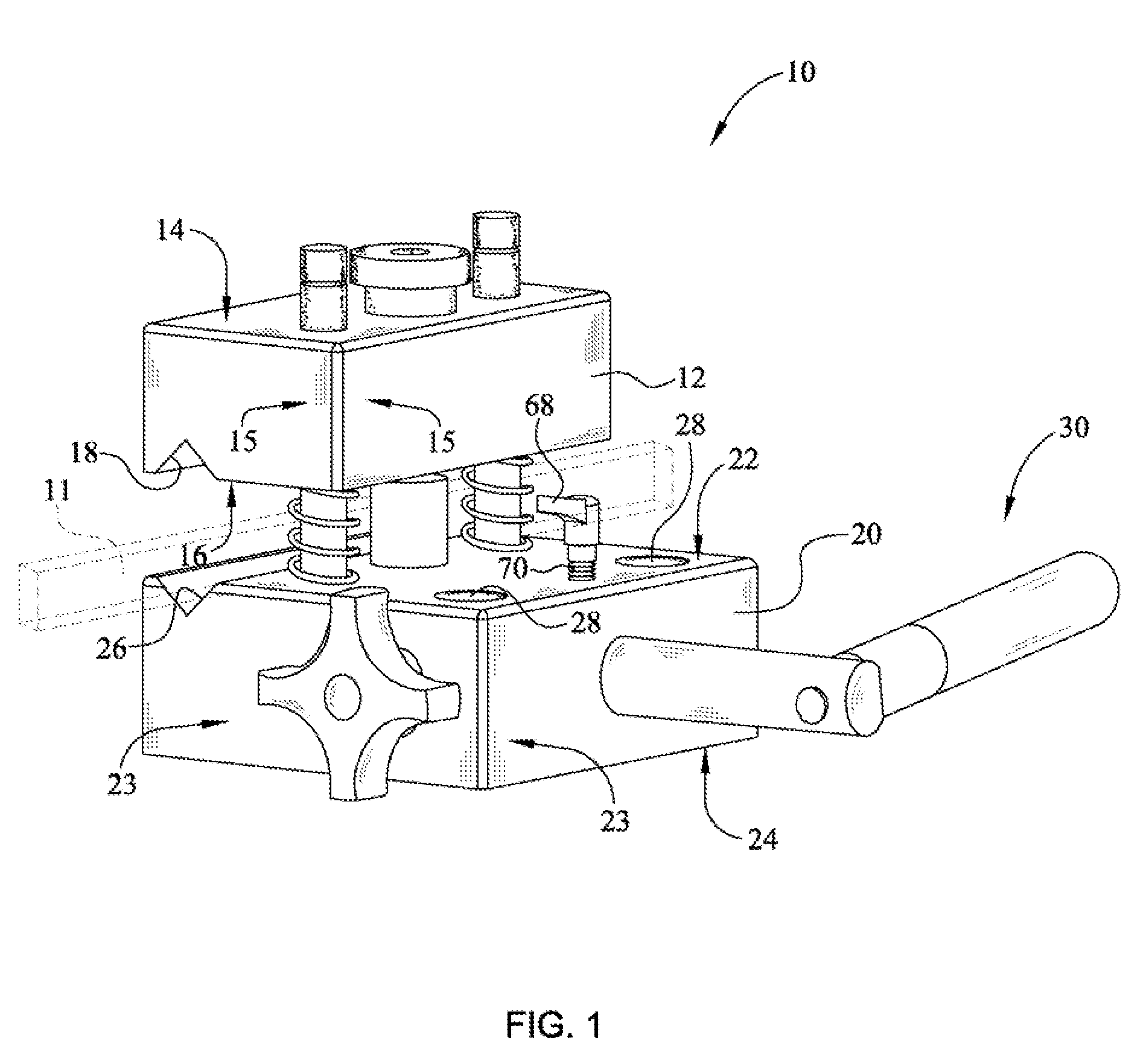
[0008]The clamp assembly of the present invention employs a stationary base clamp member and a top moving clamp member that is activated by an adjustable excenter system to provide maximum holding on the operating table rail. The operating lever is connected with the base clamp member and permeates partially or incrementally movement of the top clamp member in the upward and downward direction. The top clamp member can be moved at a desired position providing space, between the top clamp member and the base clamp member, where the rail of an operating table can be fixed.
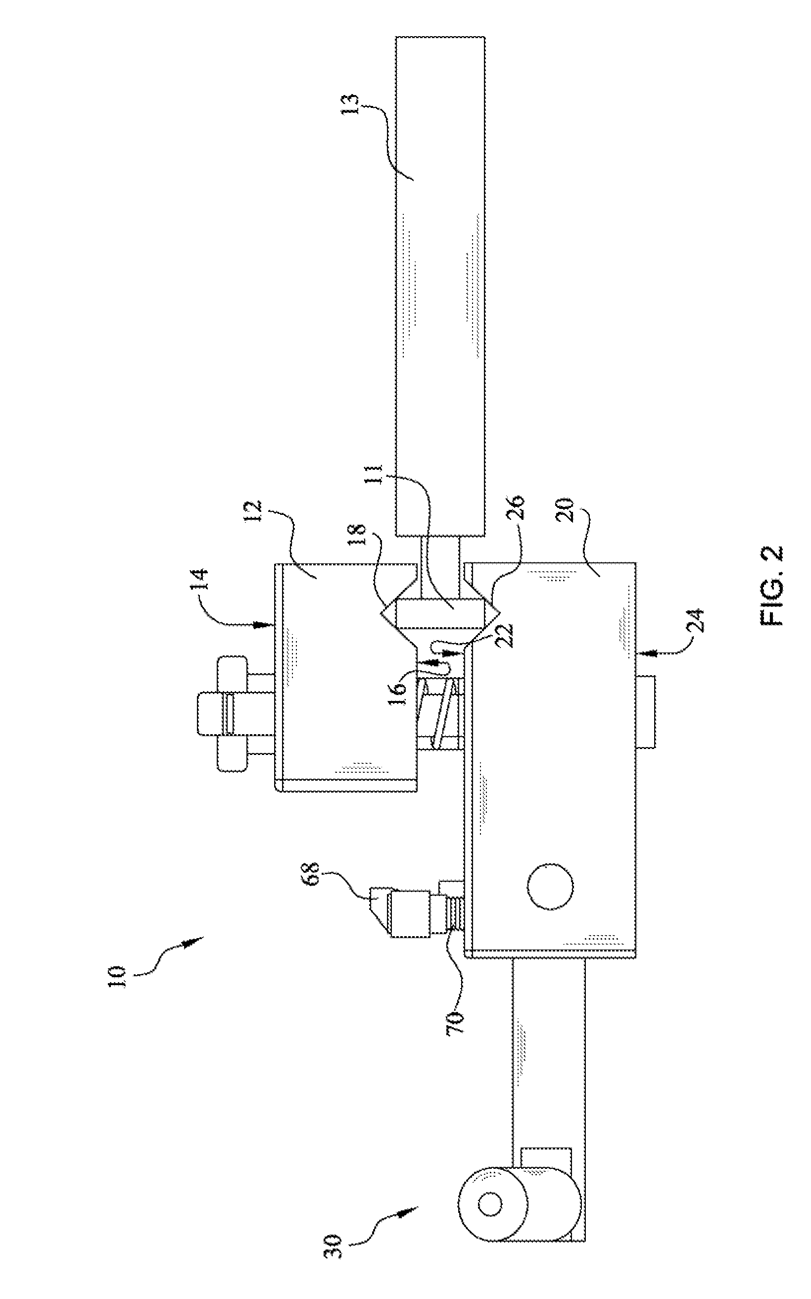
[0010]The V-shaped channels allow the clamp assembly of the present invention to be installed onto the operating table rail on the sterile side of the surgical drape allowing the sterile surgical drape to be captured between the clamp assembly and the accessory. By positioning the clamp assembly over the surgical drape, the surgeon can easily access the clamp to make small adjustments allowing more precise positioning of the support accessories. Further the V-shaped configuration of the clamp assembly provides a greater amount of space between the operating table rail and the clamp assembly allowing more layers of surgical drapes to be accommodated therein. The clamp of the present invention has been tested with up to 10 plies of surgical drape with no creep or loosening of the clamp.
[0011]The base clamp member is provided with an operating lever, dual guide pins and an actuator pin extending upwards from the upper surface of the base clamp member. Further, the top clamp member is provided with corresponding openings for receiving the guide pins and an opening for receiving the actuator pin. The dual guide pins serve to reliably position the top clamp member and the base clamp member in a parallel fashion while operating while preventing their shifting and / or torquing relative to one another once the clamp assembly is positioned and fastened. The actuator pin having a lower end engaged with the operating lever and an upper end having a threaded fastener. The activating shaft is operating the actuator pin via the excenter to move the upper clamp down to the holding position. Further, a mean for adjusting the length of the actuator pin thereby controlling the overall fastening tension is provided on the top clamp member to tighten or loosen the engagement between top and base clamp members. The operating lever moves 90 degrees to the right or to the left (clockwise or counterclockwise), from a low (engaged) to a high position (disengaged). The up and down position is created by turning the activating shaft which in turn rotates the excenter inside the actuator pin. The upper clamp base will move down or up until a secure holding position is achieved.
[0013]It is another important aspect of the invention that the base clamp member is provided with apertures to receive and retain surgical support fixtures. These apertures may be provided on any face of the lower jaw including the side surfaces allowing greater versatility and adjustability of the positioning accessories. Further, such apertures may also be provided on the top clamping member and still fall within the scope and spirit of the present invention.
[0014]Further, a safety mechanism has been provided to prevent the accidental rotation or loosening of the operating lever once the clamp assembly is installed. The safety key is provided on the base clamp member. Once the clamp assembly is installed, the safety pin is rotated to prevent further movement of the activating shaft. Rotation of the safety pin in clockwise or anticlockwise direction cause the safety pin to move at the desired downward or upward position to fix the position activating shaft. Once the safety pin is in contact with the activating shaft, it blocks further rotation of the activating shaft.
[0015]Accordingly, it is an object of the present invention to provide a clamp assembly for an operating table to be used in a sterile environment to hold different fixtures and devices. It is a further object of the present invention to provide a clamp assembly that firmly and reliably engages the left and right rails of an operating table to reliably and securely hold different fixtures and devices in the desired position.

Problems solved by technology

The difficulty with most of these prior art devices is that they have numerous moving parts and components therein that make sterilization of the device virtually impossible.
Since these devices cannot be sterilized, they are typically mounted directly to the metal side rails on the non-sterile side of the surgical drapes.
In addition, these prior art clamps cannot engage the rail when different thicknesses or additional plies of surgical drapes are utilized.
Often this ends up being the weak point in the assembly.

Method used


Image

  • Operating table support clamp
  • Operating table support clamp
  • Operating table support clamp

Examples


Embodiment Construction

[0025]Now referring to the drawings, an operating room table clamp is depicted that securely attaches to the right or left operating table rail. Once in place, various fixtures or devices may be attached onto this clamp to stabilize an upper limb, lower limb, surgical retractors and various other holding devices used during operative procedures. The clamp assembly according to one embodiment of the present invention includes a top clamp member, a base clamp member and an operating lever. The top clamp member can be moved at a desired position providing a space between the top clamp member and the base clamp member, where the rail of an operating table can be fixed. In addition, the clamp assembly can also serve as an attachment interface for apparatus other than limb positioning, such as for example, a table that can directly attach to the surgical table.

[0026]Referring to FIG. 1, a perspective view of a clamp assembly according to an exemplary embodiment of the present invention is...


PUM


Abstract

A clamp assembly for use in connection with an operating table rail is disclosed. The clamp assembly includes a top clamp member, a base clamp member and an operating lever to move the top clamp member relative to the base clamp member. The base clamp member and the top clamp member include complimentary V-shaped channels that allow the clamp assembly of the present invention to be installed on the sterile side of the surgical field. The base clamp member is provided with dual guide pins and an actuator pin, extending upwards from the base clamp member and through the top clamp member. The actuator pin is affixed with a fastening means to engage the top of the actuator pin and the base clamp member together. Further, the base clamp member includes apertures for receiving various surgical support fixtures.

Description

CROSS-REFERENCE TO RELATED APPLICATIONS[0001]This application is related to and claims priority from earlier filed U.S. Provisional Patent Application No. 60 / 891,957, filed Feb. 28, 2007.BACKGROUND OF THE INVENTION[0002]The present invention relates to a device for use in positively securing accessory devices used during surgical and other medical procedures. More specifically, the present invention relates to a clamp assembly that securely affixes to a standard surgical table to facilitate the accurate and positive positioning of accessory devices used during surgical and other medical procedures.[0003]Orthopedic surgery on the human body generally includes procedures ranging from hand, elbow, wrist, foot and ankle surgery to fracture repair. These procedures require that the joint or limb be precisely and predictably positioned during the surgical procedure. In order to achieve the most optimum positioning, the surgeon requires a large range of positive positioning adjustments tha...

Claims


Application Information

Patent Timeline
Patent Type & Authority Patents(United States)
IPC IPC(8): A47B96/06E04G3/00F16B1/00G09F7/18
CPCA61B17/02A61B19/26A61B2019/267A61B90/50A61B90/57
Inventor DASILVA, MANUEL F.
Owner DASILVA MANUEL F
Learn More