Fuel system of a handheld work apparatus

a work apparatus and fuel system technology, applied in the direction of filtration separation, separation processes, bends, etc., can solve the problems of stalling of the engine, limited suction head movement, and limited structural space available, so as to facilitate the sealing action, and reduce the effect of suction pressur

Active Publication Date: 2012-03-13
ANDREAS STIHL AG & CO KG
View PDF15 Cites 3 Cited by
  • Summary
  • Abstract
  • Description
  • Claims
  • Application Information

AI Technical Summary

Benefits of technology

[0007]It is an object of the invention to improve a fuel system of the kind described above so that an improved usage of the available fuel volume is possible even for an inclined position of the work apparatus.
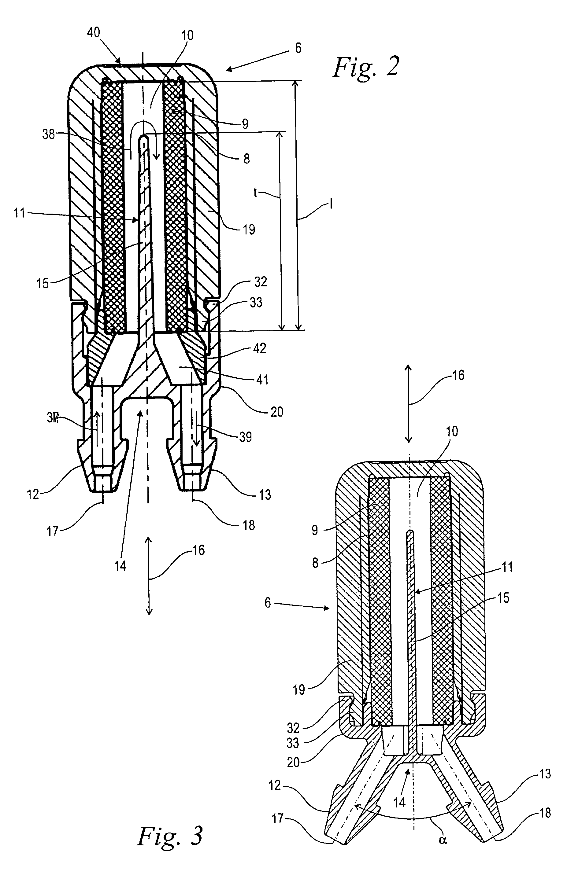
[0014]In an advantageous further embodiment, the porous covering extends in a longitudinal direction and has a length. Here, the partition wall projects to a depth into the suction space which extends over approximately 50% of the length of the porous covering and especially over at least 75% thereof. In this way, a flow short circuit from inlet to outlet is avoided within the suction space so that the through-passing fuel flow is compelled to touch the entire interior surface of the porous covering.
[0015]In an advantageous embodiment, the longitudinal axes of the inlet and outlet are parallel to each other. Alternatively, it can be practical that these axes lie at an angle with respect to each other. This angle (α) lies in a range from 45°≦α≦90° and is especially approximately 60° . For an axial parallel configuration of the inlet and outlet, the line segments connected thereto can be held very close to each other so that the corresponding suction head can be introduced into very narrow regions of the fuel tank and can there maintain its movability. Very small construction volumes for the base body of the second suction head are achievable for the angled arrangement of the longitudinal axes of inlet and outlet.
[0016]In a preferred embodiment, the porous covering is held within a frame as disclosed in U.S. Pat. No. 5,441,637 incorporated herein by reference. The inlet, the outlet and the partition wall are joined as one piece to a cover. The cover is connected to the frame and is especially latched thereto. With the one-piece configuration of inlet, outlet and partition wall, a clean flow guidance is possible without additional sealing measures. The connection between the cover and the frame can be configured without such sealing measures in a simple manner. The latching simplifies the cost-effective series manufacture and nonetheless ensures a reliable function.
[0017]Preferably, the porous covering extends closed in the peripheral direction of the second suction head and is especially configured so as to be cylindrical. In this way, a specific angular position is not important during the installation. Rather, a uniform fuel induction takes place distributed over the periphery. The low through-flow resistance associated therewith accommodates the low available suction pressure. Furthermore, a maximum of fuel is held in the porous covering as a consequence of the capillary action whereby the seal tightness thereof can be maintained permanently or at least over a very long time span without external wetting.
[0019]Various materials can be used for configuring the porous covering such as lattices, sieves or the like insofar as they can provide a capillary action to hold fuel. Preferably, the porous covering is formed by a sinter body. This body can be configured with a corresponding thickness without generating an excessively high through-flow resistance. As a consequence of its significant thickness, a three-dimensional form body is provided which can store a larger quantity of fuel via capillary action which facilitates the sealing action in the dry state. This becomes especially effective when the fuel pump is a membrane pump. The suction pressure is comparatively slight compared to a gear pump or the like. The capillary action of the suction head lying above the fuel surface can withstand this low suction pressure so that the sealing action of the fuel wetting remains notwithstanding the applied pressure difference.

Problems solved by technology

Otherwise, the mixture can become lean and, in the extreme case, this can lead to a stalling of the engine.
The structural space available often compels construction wherein the fuel tank is configured comparatively wide transversely to the up direction and wherein the interior space of the fuel tank has numerous geometric irregularities.
Although the suction head can lie on the base because of its own weight, for an inclined position, however, the suction head can move laterally only to a limited extent.
The typical design of portable handheld work apparatus is made difficult in that the fuel pump only has a low pumping capacity and that only low suction pressures are available.
Even a short-term case of the suction head becoming dry can lead to the situation that the associated air induction leads to operational disturbances or even to stalling of the engine.

Method used


Image

  • Fuel system of a handheld work apparatus
  • Fuel system of a handheld work apparatus
  • Fuel system of a handheld work apparatus

Examples


Embodiment Construction

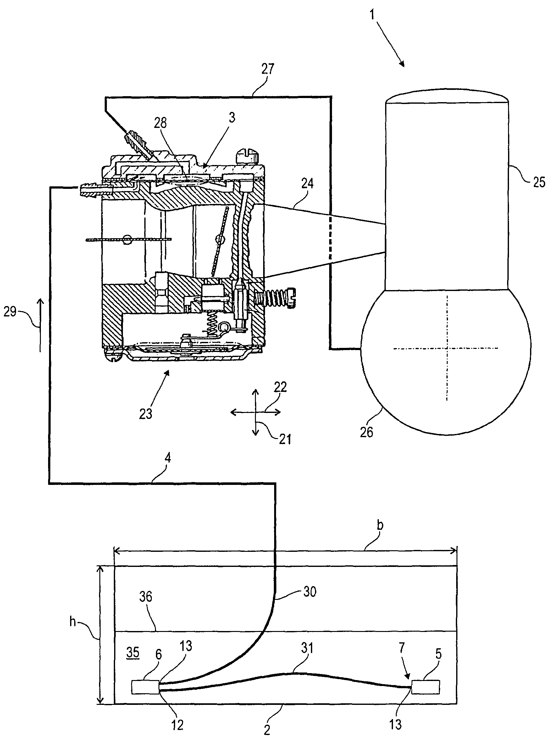
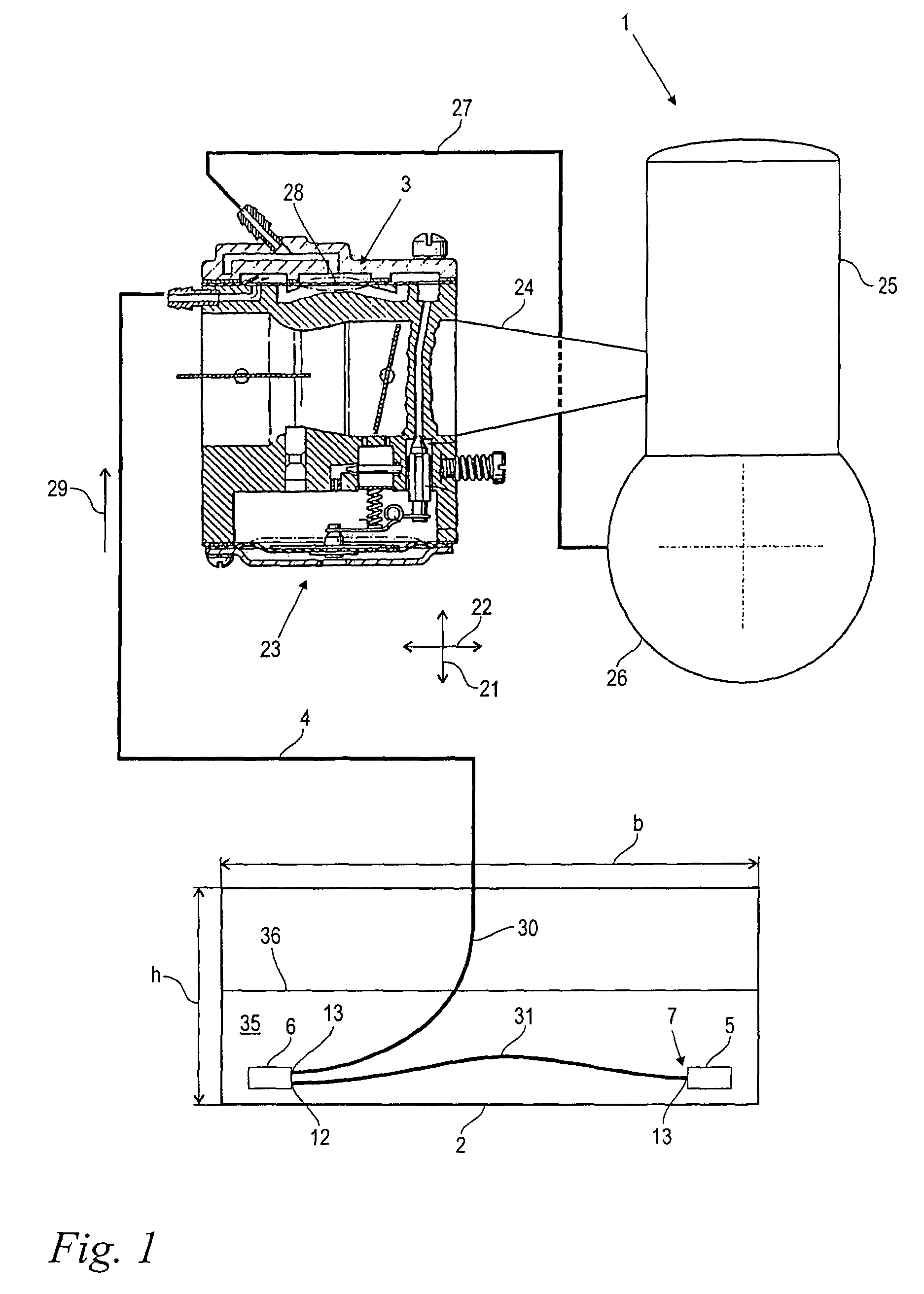
[0026]FIG. 1 shows a schematic block diagram of the fuel system of the invention. The fuel system is for a portable handheld work apparatus driven by an internal combustion engine 1 which is provided for operation by a user when carried on the back or when hand carried. Such a work apparatus can, for example, be a blower / suction apparatus, a chain saw, a brushcutter or the like.

[0027]The schematically represented internal combustion engine 1 is shown as a single-cylinder two-stroke engine in the embodiment shown; however, the engine can also be a four-stroke engine and includes a cylinder 25 as well as a crankcase 26. A carburetor 23 is provided for forming an air / fuel mixture which supplies the engine 1 with the formed air / fuel mixture via an intake channel 24.

[0028]Fuel 35 is held in a fuel tank 2 for the operation of the engine 1 and forms a fuel level 36. The fuel 35 is drawn by suction from the fuel tank 2 by a fuel pump 3 and is conveyed to the carburetor 23. In the embodiment...


PUM

PropertyMeasurementUnit
angleaaaaaaaaaa
angleaaaaaaaaaa
angleaaaaaaaaaa

Abstract

The invention relates to a fuel system of a portable handheld work apparatus driven by an internal combustion engine. The fuel system includes a fuel tank (2), a fuel pump, a fuel line (4) leading from the fuel tank (2) to the fuel pump and a first suction head (5) which is disposed at an end (7) of the fuel line (4) at the fuel tank. At least a second suction head (6) is arranged within the fuel tank (2) and is connected in the fuel line (4) in series ahead of the first suction head (5). The second suction head (6) has an external suction surface which is formed by a porous covering (9). The porous covering (9) delimits a suction space. A guide is arranged in the suction space which guides the through-passing fuel flow at least approximately along the entire inner surface of the porous covering (9).

Description

CROSS REFERENCE TO RELATED APPLICATION[0001]This application claims priority of German patent application no. 10 2008 058 498.3, filed Nov. 24, 2008, the entire content of which is incorporated herein by reference.FIELD OF THE INVENTION[0002]The invention relates to a fuel system of a hand-guided work apparatus driven by an internal combustion engine.BACKGROUND OF THE INVENTION[0003]Work apparatus of this kind include a fuel tank wherein the fuel is stored for the operation of the internal combustion engine. Fuel is drawn by suction from the fuel tank by means of a fuel pump and is supplied to the carburetor of the engine in order to be there processed to an ignitable air / fuel mixture. For a clean mixture formation and a reliable running of the engine, it is necessary that the fuel be drawn free of bubbles. Otherwise, the mixture can become lean and, in the extreme case, this can lead to a stalling of the engine.[0004]A lower-lying region of the fuel tank is selected wherein the fue...

Claims


Application Information

Patent Timeline
Patent Type & Authority Patents(United States)
IPC IPC(8): F02M37/04F16L43/00B01D27/00
CPCF02M37/007F02M37/0082F02M37/046Y10T137/2754Y10T137/2829
Inventor JOOS, STEFFENLANGHANS, KLAUS
Owner ANDREAS STIHL AG & CO KG
Why Eureka
Try Eureka