Tooth mold retaining frame

a technology of tooth molds and retaining frames, which is applied in the field of tooth mold retaining frames, can solve the problems of affecting the quality of tooth molds, so as to avoid the error in the manufacturing process of tooth molds and be convenient to view

Inactive Publication Date: 2010-03-30
SONG YOUNG INT
View PDF2 Cites 7 Cited by
  • Summary
  • Abstract
  • Description
  • Claims
  • Application Information

AI Technical Summary

Benefits of technology

[0004]Accordingly, the primary object of the present invention is to provide a tooth mold retaining frame, wherein by a universal connector, the upper teeth mold can move three directionally and can lift or descend proportionally so as to avoid the error in manufacturing of the teeth mold. Thus the teeth mold can be made precisely and the condition of the teeth mold can be viewed conveniently. Furthermore, the teeth mold can be sent directly without needing to send the teeth frame. Thus, the manufacturer can make the teeth mold continuously without affecting the working time.
[0005]To achieve above objects, the present invention provides a tooth mold retaining frame comprising: an L shape seat; two lateral sides of the L shape seat being extended from the button seat and a supporting frame being installed above the two lateral sides; each of two ends of the supporting frame having a retaining groove; a pivotal block having a pivotal rod and a connecting portion; two ends of the pivotal rod being secured to the two retaining grooves of the supporting frame; a universal connector; one end of the universal connector being connected to the connecting portion of the pivotal block; a first positioning block; a lower side of the first positioning block having a protrusion and at least one nose; the first positioning block being connected to the universal connector; the first positioning block being movable with respect to the universal connector; a second positioning block being positioned on the lower seat and having a protrusion and at least one nose; and a first fine adjust unit including a top plate and an adjust button; the top plate being connected to the pivotal block; the adjust button passing through the supporting frame and one end thereof resisting against the top plate so that the top plate moves longitudinally to drive the pivotal block, universal connector and the first positioning block; a fine-adjust device installed on the L shape seat by using an adjust screw to adjust the second positioning block to move leftwards or rightwards; and a second positioning block including a telescopic rod one end of which is installed to the L shape seat and another end of which resists against the pivotal block; the telescopic rod having an adjust button for adjusting a length of the telescopic rod so as to adjust the position of seat; wherein by using the first fine adjust unit, second fine adjust unit and the fine-adjust device, an upper teeth mold, and a lower teeth mold can move with respect to one another precisely.

Problems solved by technology

However the teeth molds T and T′ will have different compression ratios due to different solidifying states so that errors in biting are induced.
The precision in the manufactured denture is not good.
Each tooth mold retaining frame has errors in the manufacturing process.
However the tooth mold retaining frame can not be used to make another teeth mold during this time period.

Method used


Image

  • Tooth mold retaining frame
  • Tooth mold retaining frame
  • Tooth mold retaining frame

Examples


Embodiment Construction

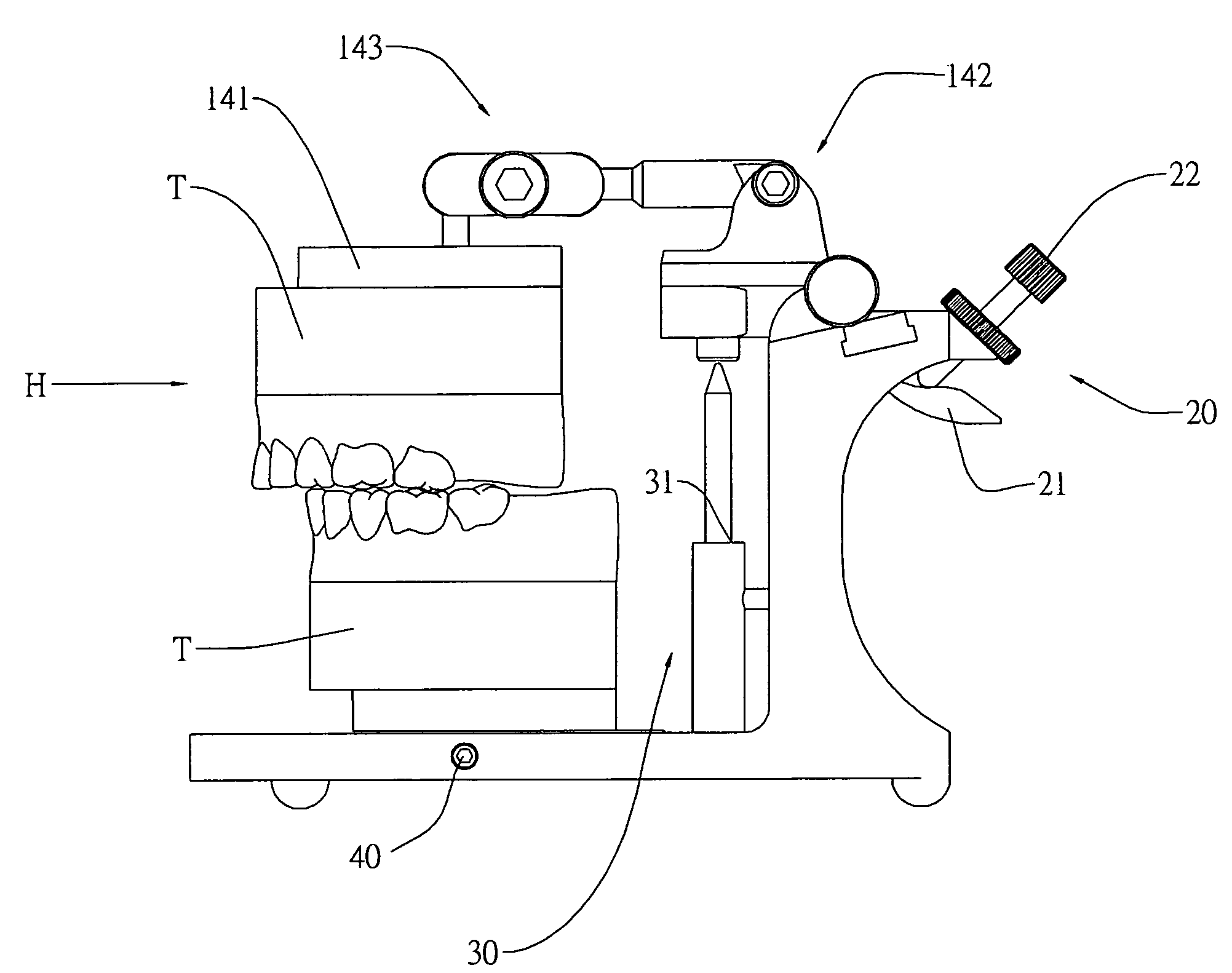
[0011]In order that those skilled in the art can further understand the present invention, a description will be provided in the following in details. However, these descriptions and the appended drawings are only used to cause those skilled in the art to understand the objects, features, and characteristics of the present invention, but not to be used to confine the scope and spirit of the present invention defined in the appended claims. Referring to FIGS. 2 and 3, the structure of the present invention is illustrated. The present invention has the following elements.

[0012]An L shape seat 10 has a lower seat 17, a pivotal block 111, an universal connector 143, a first positioning block 141, a second positioning block 13, a first fine adjust unit 20, a second fine adjust unit 30, and a fine-adjust device 40. Two lateral sides 11 are extended from the button seat 17 and a supporting frame 12 is installed above the two lateral sides 11. Each of two ends of the supporting frame 12 has...


PUM

PropertyMeasurementUnit
lengthaaaaaaaaaa
shapeaaaaaaaaaa
timeaaaaaaaaaa

Abstract

A tooth mold retaining frame comprises an L shape seat; a pivotal block; a universal connector; a first positioning block; a second positioning block; and a first fine adjust unit. By using the first fine adjust unit, second fine adjust unit and the fine-adjust device, an upper teeth mold, and a lower teeth mold can move with respect to one another precisely. By a universal connector, the upper teeth mold can move three directionally and can lift or descend proportionally so as to avoid the error in manufacturing of the teeth mold. Thus the teeth mold can be made precisely and the condition of the teeth mold can be viewed conveniently. Furthermore, the teeth mold can be sent directly without needing to send the teeth frame. Thus, the manufacturer can make the teeth mold continuously without affecting the working time.

Description

FIELD OF THE INVENTION[0001]The present invention relates to teeth mold retaining frames, and particularly to a tooth mold retaining frame, wherein by a universal connector, the upper teeth mold can move three directionally and can lift or descend proportionally so as to avoid the error in manufacturing of the teeth mold. Thus the teeth mold can be made precisely and the condition of the teeth mold can be viewed conveniently. Furthermore, the teeth mold can be sent directly without needing to send the teeth frame. Thus, the manufacturer can make the teeth mold continuously without affecting the working time.BACKGROUND OF THE INVENTION[0002]Referring to FIG. 1, a prior art tooth mold retaining frame 90 is illustrated. A seat 91 is pivoted with an upper seat 92 at an upper end thereof. A lower end of the seat has a lower seat 93. The upper seat 92 has a positioning block 921 and the lower seat 93 has a positioning block 931. The positioning blocks 921, 931 have respective magnets. A s...

Claims


Application Information

Patent Timeline
Patent Type & Authority Patents(United States)
IPC IPC(8): A61C19/00
CPCA61C11/08A61C11/084A61C11/06
Inventor LIN, CHAO-HUNG
Owner SONG YOUNG INT
Why Eureka
Try Eureka