Supporting mechanism of reflector and projection apparatus

a technology of projection apparatus and support mechanism, which is applied in the direction of projectors, mountings, instruments, etc., can solve the problems of large distortion in the output image of the projector, and achieve the effects of preventing the occurrence of large distortion in the optical image projected by the projection apparatus, reducing costs, and minimizing the shape of the reflection surface of the reflector

Inactive Publication Date: 2010-03-30
MITSUBISHI ELECTRIC CORP
View PDF21 Cites 13 Cited by
  • Summary
  • Abstract
  • Description
  • Claims
  • Application Information

AI Technical Summary

Benefits of technology

[0008]According to the present invention, even when the temperature, humidity or the like changes, the reflector (a mirror or the like) freely expands and contracts about the pivot supporting portion. Therefore, the distortion may hardly occur in the reflector, and the deformation of the shape of the reflection surface of the reflector can be minimized. As a result, the occurrence of the large distortion in the optical image projected by the projection apparatus can be prevented. Further, the reflector is supported by the pivot supporting portion provided at one place, and therefore the position of the reflector can freely be adjusted, irrespective of the accuracy of components such as the reflector, supporting parts thereof or the like. As a result, the cost can be reduced.

Problems solved by technology

As a result, if there is a change in temperature, humidity or the like, there is a problem that the distortion may occur in an optical image emitted by the projection apparatus, and therefore a large distortion may occur in an output image of the projector.

Method used


Image

  • Supporting mechanism of reflector and projection apparatus
  • Supporting mechanism of reflector and projection apparatus
  • Supporting mechanism of reflector and projection apparatus

Examples


embodiment 1

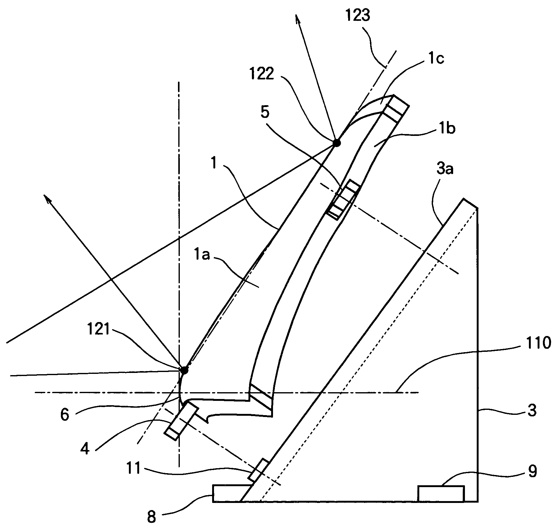
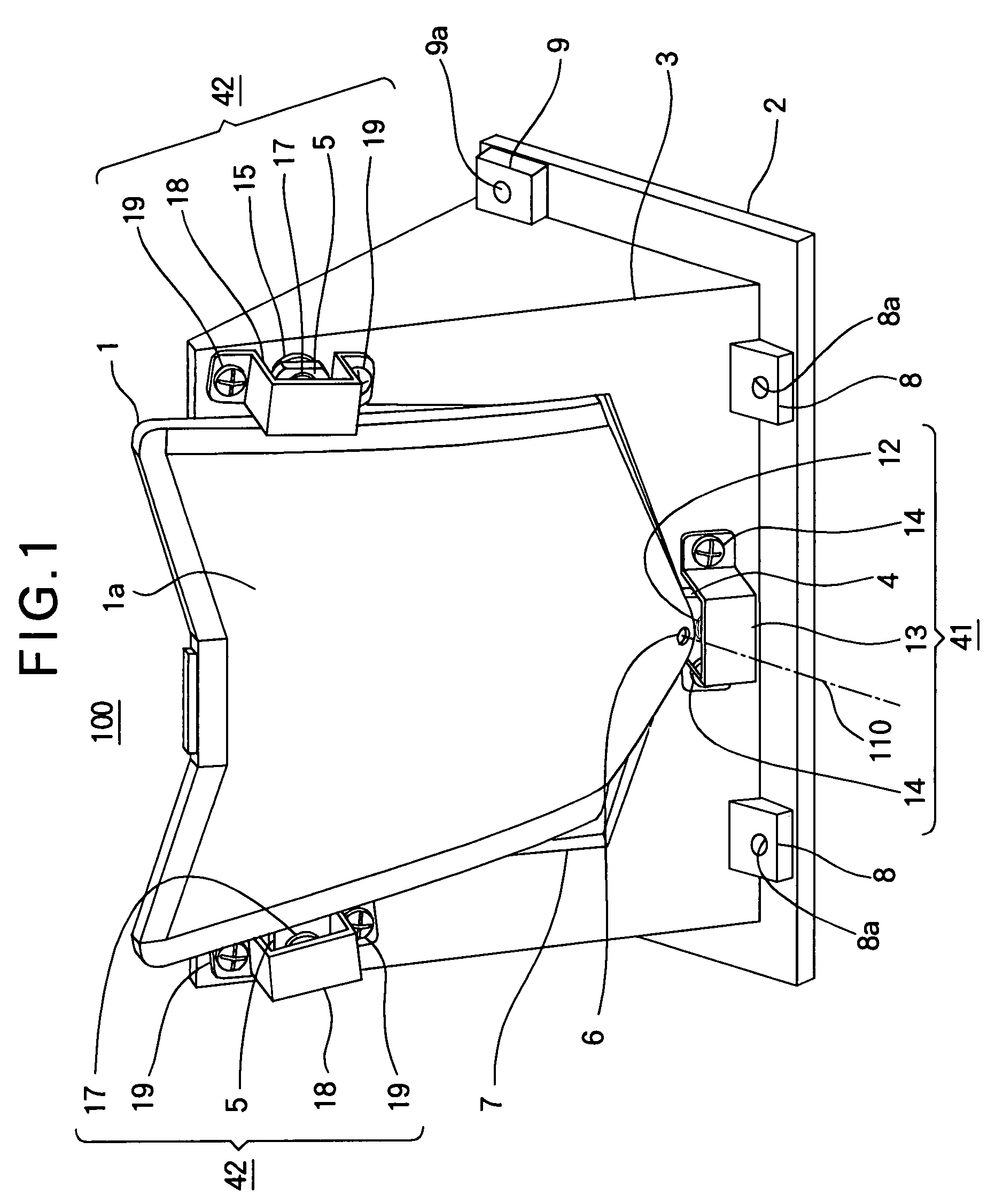
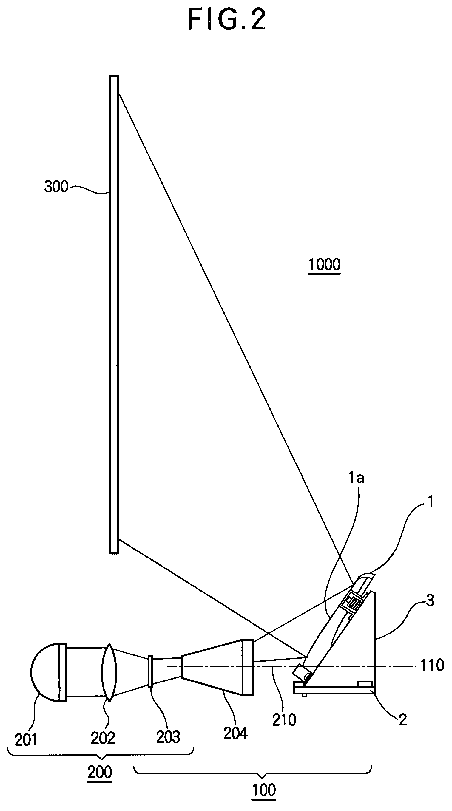
[0026]Hereinafter, Embodiment 1 of the present invention will be described with reference to the drawings. FIG. 1 is a perspective view of a supporting mechanism of a mirror (reflector) 1 according to Embodiment 1 of the present invention. FIG. 2 is a perspective view of a projector including a projection apparatus having the supporting mechanism of the mirror according to Embodiment 1. FIG. 3 is a perspective view of the mirror according to Embodiment 1. FIG. 4 is a side view of the mirror according to Embodiment 1. FIG. 5 is a side view showing the supporting mechanism of the mirror according to Embodiment 1 in an exploded manner. FIG. 6 is a cross-sectional view of a pivot supporting portion of the supporting mechanism of the mirror according to Embodiment 1. FIG. 7(A) is a longitudinal sectional view of a slide supporting portion of the supporting mechanism of the reflector according to Embodiment 1. In FIGS. 1 through 7, the same components are assigned the same reference numer...

embodiment 2

[0048]In the above described Embodiment 1, as was described with reference to FIG. 7(A), the slide supporting portion 42 is provided with the adjusting mechanism for adjusting the supporting position of the mirror (i.e., the reflector) 1. More specifically, the adjusting screw 16 is constructed by the member having the end portion 16b contacting the end portion 15b of the contact pin 15, and the adjusting screw 16 engages the fixing member 3, so that the supporting position of the mirror 1 can be adjusted by rotating the adjusting screw 16. In this Embodiment, the same adjusting mechanism is provided on the pivot supporting portion 41, so as to obtain the same advantage. More specifically, as shown in FIG. 7(B), an adjusting screw 11b (which is the same as the above described adjusting screw 16) constitutes the receiving portion 11 having a bowl-shaped receiving surface 11a contacting the end portion 10b of the pivot pin 10, and the adjusting screw 11b engages the threaded hole of t...

embodiment 3

[0049]Hereinafter, Embodiment 3 of the present invention will be described with reference to drawings. FIG. 8 is a cross-sectional view cut in the horizontal direction and as seen from below, showing a supporting mechanism of a pivot supporting portion 43 supporting the first lug 4 in this Embodiment. The supporting mechanism of the pivot supporting portion 43 has the configuration that differs from the supporting mechanism of the pivot supporting portion 41 (FIG. 6) described in Embodiment 1. FIG. 9 is a longitudinal sectional view cut in the horizontal direction and as seen from the side, showing a supporting mechanism of the slide supporting portions 42. The supporting mechanism of the slide supporting portions 42 has the configuration that differs from the supporting mechanism of the slide supporting portions 42 (FIG. 7) described in Embodiment 1. In respective parts shown in FIGS. 8 and 9, respective portions that are the same as or corresponding to the portions shown in FIGS. ...


PUM


Abstract

A reflection surface (1a) of a mirror (1) has a rotationally-symmetrical shape about an optical axis (110). The mirror (1) is rotatably supported by a pivot supporting portion (41) on the position of the optical axis (110) of the reflection surface (1a) or in the vicinity of the optical axis (110). Furthermore, the mirror (1) is slidably supported by slide supporting portions (42) at two positions on the upper part thereof. With such a configuration, the mirror (1) is supported at three points. Further, even when the mirror (1) expands and contracts due to the change in temperature or the like, the deformation of the reflection surface (1a) of the mirror (1) is prevented by the action of the slide supporting portions (42). As a result, it is possible to prevent the generation of distortion of an image projected on a screen (300).

Description

TECHNICAL FIELD[0001]This invention relates to a supporting mechanism of a reflector of a projection apparatus used in, for example, a projector or the like, and relates to a projection apparatus using same.BACKGROUND ART[0002]In a projection apparatus used in a projector, a mirror having a reflection surface needs to be disposed in the projection apparatus with a high positioning accuracy. Therefore, conventionally, the mirror is fixed onto a fixing member provided in the projection apparatus by means of a number of screws or the like. For this reason, if the mirror expands and contracts due to the change in temperature, humidity or the like, a stress may be originated from a portion fixed by the screw may be accumulated inside the mirror, and the shape of the reflection surface of the mirror may be deformed by the stress. As a result, if there is a change in temperature, humidity or the like, there is a problem that the distortion may occur in an optical image emitted by the proje...

Claims


Application Information

Patent Timeline
Patent Type & Authority Patents(United States)
IPC IPC(8): G03B21/28
CPCG02B7/181G02B7/182G03B21/10G03B21/28
Inventor AIZAWA, JYUNICHIMIYATA, AKIHISA
Owner MITSUBISHI ELECTRIC CORP
Why Eureka
Try Eureka