Tie-down anchor system and method

a technology of tie-down anchors and rings, which is applied in the field of tie-down anchor systems and methods, can solve the problems of permanent damage to the surface, difficult manufacturing, and difficult mounting of prior art systems, and achieve the effects of minimal failure, maximum convenience and strength, and minimal failur

Inactive Publication Date: 2010-03-30
BLACKGRAY DESIGNMFG
View PDF7 Cites 19 Cited by
  • Summary
  • Abstract
  • Description
  • Claims
  • Application Information

AI Technical Summary

Benefits of technology

[0007]The present invention relates to a family of anchor devices that include a back plate mounted behind a mounting surface with a flange mounted in front of the mounting surface and generally a ring or hook carrier member that engages an anchor ring or a hook. In several embodiments of the present invention, the carrier can rotate without the use of axles or pins allowing the load to align the device in a direction of maximum convenience and strength. The lack of axles or pins as a means to achieve rotation between two objects also leads to minimal failures and maximum longevity. A first embodiment provides a rotating ring in a recessed retaining cup that provides for maximum flexibility and is intended to be relatively flush with the mounting surface. A second embodiment provides a rotating ring in a clip carrier in a raised mounting flange. A third embodiment provides a swivel insert hook carrier that can rotate. A fourth embodiment includes a ring that engages a notch in a raised carrier. Fifth and sixth embodiments provide attachments for one or multiple hooks in a fixed-mounted, non-rotating flange.

Problems solved by technology

Many of these prior art systems have the disadvantage of being difficult to mount because in general they require recessing in the mounting surface.
Recessing necessitates cutting a large hole in the surface which possibly permanently damages the surface and weakens it.
Another disadvantage of the prior art systems is that they are complex and difficult to manufacture.
Finally, some of the prior art systems cannot carry the loads required of modern tie-down anchors, and many use axles or pins to achieve rotation which can lead to possible failure.

Method used


Image

  • Tie-down anchor system and method
  • Tie-down anchor system and method
  • Tie-down anchor system and method

Examples


first embodiment

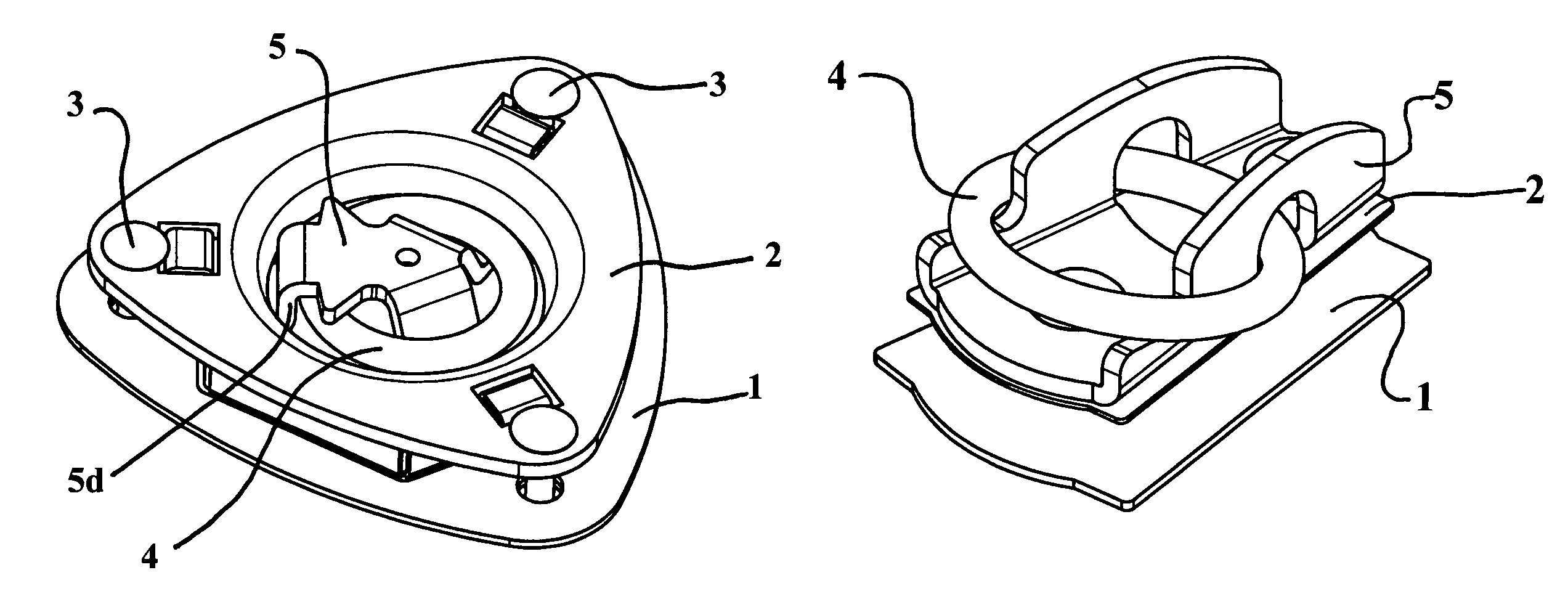
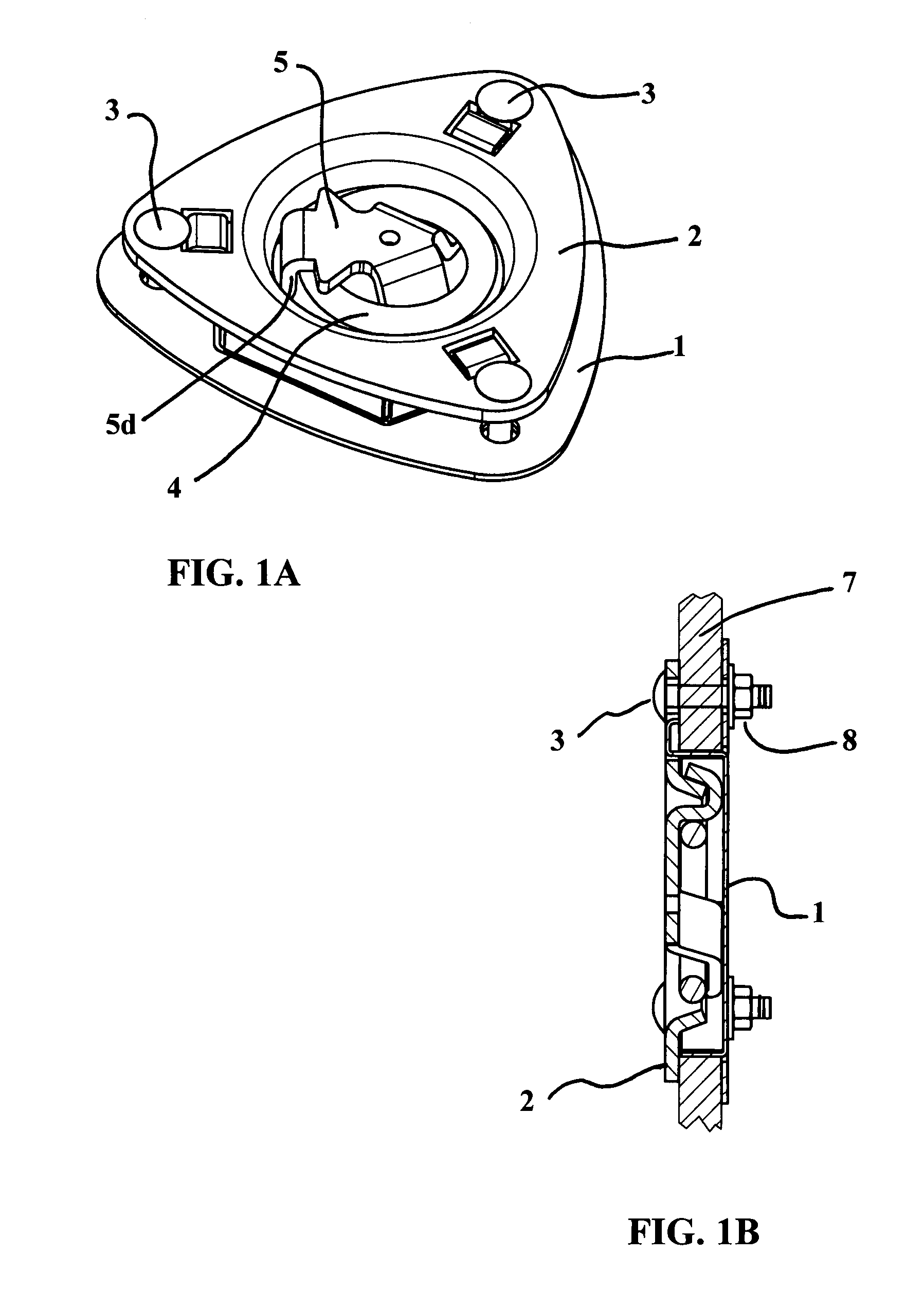
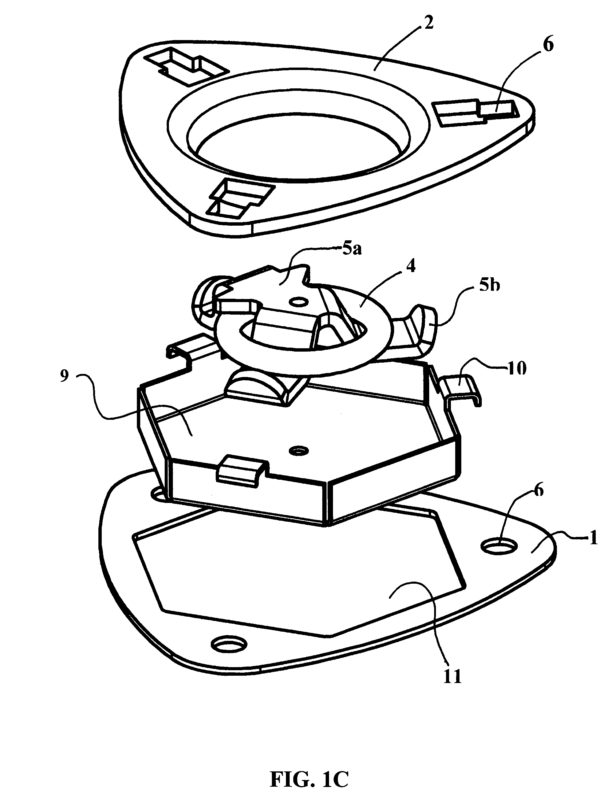
[0040]Turning to FIGS. 1A-1E, the invention can be seen. FIG. 1A shows a perspective view of this embodiment. This particular embodiment requires a recess in the mounting surface 7 for the anchor device. The recess must be large enough to allow the retaining cup 9 shown in FIG. 1C to pass through. A backing plate 1 that is normally mounted behind the mounting surface cooperates with a top mounting flange 2 that is secured through the surface to the plate 1 with three bolts 3 to tightly mount the device. The preferred bolt is a 5 / 16-18 carriage bolt; however, any bolt is within the scope of the present invention. The mounting flange 2 contains square holes 6 that receive the carriage bolts and prevent rotation when securing fasteners / hex nuts 8. The “double-square” shaped holes accept and reveal the tabs of the retaining cup and the heads of the carriage bolts function to fasten and clamp the retaining cup. These holes 6 can be adapted to allow space for attachment flanges 10 (FIG. 1...

second embodiment

[0043]Turning to FIGS. 2A-2E, the invention can be seen. This embodiment also provides a rotating ring without the use of axles or pins; however, this embodiment does not require recessing. A flat backing plate 1, with normally no holes other than the bolt holes 6, in cooperation with a top mounting flange 2 sandwiches a surface 7 using bolts 3 and nuts 8. The flange 2 has a raised area 2a with lower supports 2b that transition through steps 2c. The raised area 2a provides space for a rotating mount 5 to be held in place but still free to rotate.

[0044]The rotating mount 5 has a flat top area 5a with descending sides 5f and at least two flat feet 5b (FIG. 2C). One end of this rotating mount 5 can contain a protruding nose 5c with a descending lip 5d and notch 5e. The legs 5b hold the rotating mount 5 under the mounting flange 2, while the particular shape of the mounting flange 2 allows the mount 5 to rotate by not pinching it. The notch 5e and descending lip 5d receive an anchor rin...

fourth embodiment

[0047]the present invention is shown in FIGS. 4A-4G and includes a pair of flat plates, namely a front plate 2 and a back plate 1 that engage and sandwich a mounting surface 7. A ring clip 5 mounts above the front plate 2 trapping / retaining an anchor ring 4 with a pair of bolts 3 passing through the ring clip 5, the top plate 2 and the back plate 1. These bolts 3 receive nuts 8 to mount the arrangement. An anchor ring 4 passes through a notch 5e in the ring clip 5. The ring 4 is free to rotate forward and backward in this notch 5e. The preferred bolt is a 5 / 16-18 carriage bolt with a washer and a 5 / 16-18 nut. Any type of bolts and nuts are within the scope of the present invention.

[0048]Turning to FIGS. 5A-5C and 6A-6C, a fifth and sixth embodiment of the present invention can be seen. In these embodiments, a back plate 1 and front plate 2 sandwich a mounting surface 7. The front plates have holes in a raised center section to receive hooks. In the fifth embodiment (FIGS. 5A-5C), th...


PUM


Abstract

A family of anchor devices that include a back plate mounted behind a mounting surface with a flange mounted in front of the mounting surface and generally a ring or hook carrier member that engages an anchor ring or a hook. In several embodiments the carrier can rotate without axles pins or the like allowing the load to align the device in a direction of maximum convenience and strength. A first embodiment provides a rotating ring in a recessed retaining cup that provides for maximum flexibility. A second embodiment provides a rotating ring in a clip carrier in a raised mounting flange. A third embodiment provides a swivel insert hook carrier that can rotate. A fourth embodiment includes a ring that engages a notch in a raised carrier. Fifth and sixth embodiments provide attachments for one or multiple hooks in a fixed-mounted, non-rotating flange.

Description

BACKGROUND[0001]1. Field of the Invention[0002]The present invention relates generally to the field of tie-down anchors and rings and more particularly to a tie-down anchor system and method that comprises a family of related tie-downs.[0003]2. Description of the Prior Art[0004]Tie-down anchors and anchor rings are used to secure loads to solid structures such as tying down a motorcycle in a truck or securing any type of movable object or cargo so it cannot move especially when it is being hauled in a moving vehicle.[0005]Several different tie-down anchors have been used in the art. For example, McDaid in U.S. Pat. No. 6,138,975 teaches an anchored tie-down that mounts in concrete. Lewis in U.S. Pat. No. 3,412,693 teaches a simple ring / plate anchoring device secured to a surface with wood screws. Fenner in U.S. Pat. No. 4,630,982 teaches a receptacle that is incorporated into an aircraft floor. Akright describes a tie-down assembly in U.S. Pat. No. 4,907,921 that houses a tie-down r...

Claims


Application Information

Patent Timeline
Patent Type & Authority Patents(United States)
IPC IPC(8): B60P7/08
CPCB60P7/0807
Inventor GRASSO, ANDRE'
Owner BLACKGRAY DESIGNMFG
Why Eureka
Try Eureka