Precision positioning and fastening system
a technology of positioning and fastening, applied in the direction of locking fasteners, bolts, light support devices, etc., can solve the problems of time-consuming and labor-intensive removal of dowels, axial force, and inability to meet the requirements of the application
- Summary
- Abstract
- Description
- Claims
- Application Information
AI Technical Summary
Benefits of technology
Problems solved by technology
Method used
Image
Examples
first embodiment
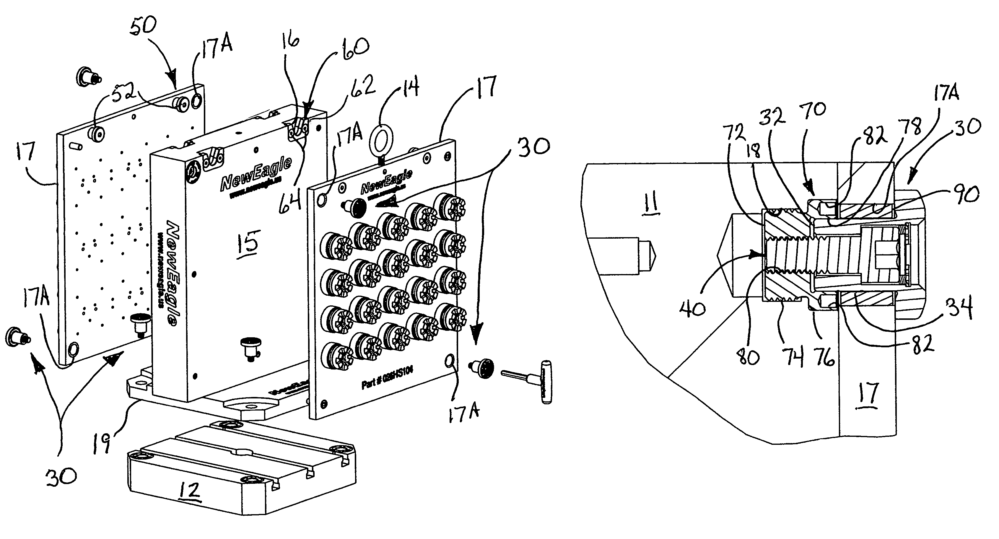
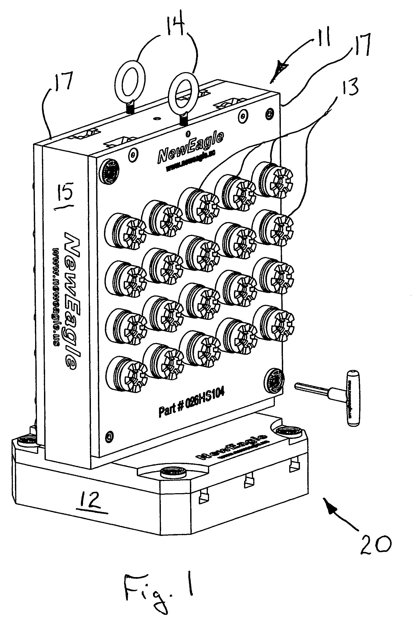
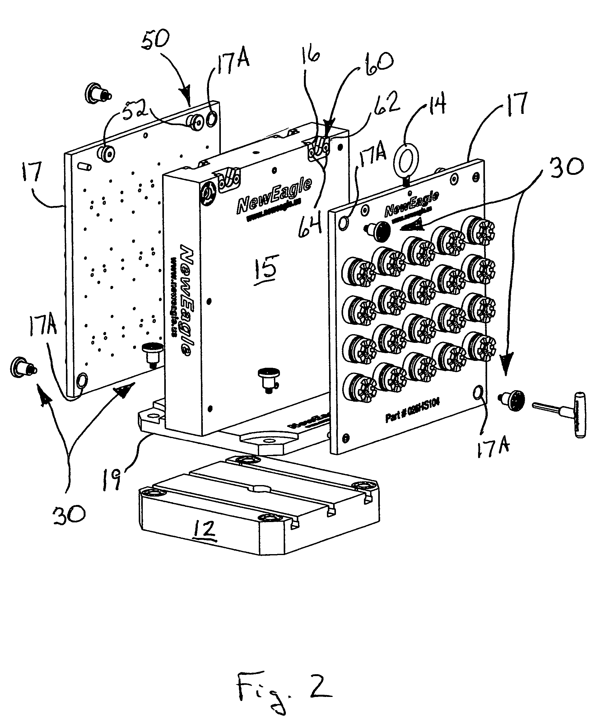
[0035]the locating and fastening system of the present invention is depicted in FIGS. 1 and 2 generally at 20. The locating and fastening system 20 of the present invention includes locator / fasteners 30 and a hanger system 50. As depicted in FIGS. 1 and 2, locating and fastening system 20 is used with a workholding chassis or tombstone 11 has secured thereto a number of workpieces 13 for performing machining operations thereon. Tombstone 11 includes a base 15 and two sub-base plates 17 from which workpieces 13 are suspended. Each sub-base plate 17 has a plurality of throughbores with a first set of center-lines 17A. Base 11 has flange 19 extending from either side which is attached to mounting plate 12. Flange 19 can be formed as a separate member and attached to base 11 or may be formed integrally therewith. Eyelets 14 are provided to enable sub-base plates 17 to be lifted and placed upon base 11. Locator / fasteners 30 can be used to fix flange 19 of base 11 to mounting plate 12.
[00...
second embodiment
[0040]receiver is shown in FIGS. 5A, 5B generally at 70′. In this embodiment, rather than having integral threads on cylindrical body portion 72′, separate threaded fasteners 21′ engage through holes 75′ in head portion 76′ to secure it in opening in base 11′. FIG. 5B depicts an important feature of each of these receivers and locator fasteners. As seen there, lead end 35 of locator 32 is formed with an angular surface 82′. This angular surface 82′ may take the form of a chamfer or radiused surface. A complimentarily shaped surface 79′ is formed in the precision-machined opening 78′ in head portion 76′. These complementary surfaces enable the locator 32 to adjust for mis-alignment between the base 11 and sub-plate 17 which produces mis-alignment between the receiver 70′ and the locator / fastener 30. The combination of these cooperating angular surfaces 79′ and 82′ and the floating of fastener 40 within the throughbore 38, enable these misalignment difficulties to be overcome.
third embodiment
[0041]FIG. 6 shows yet receiver shown generally at 70″. This receiver 70″ is installed on the opposite side of base 15″ using a press fit. Obviously, body 72″ could be threaded or separate fasteners could be employed; however, since fastener 40 will pull the receiver 72″ against the rear portion of sub-base plate 17″, these additional fastening means are unnecessary.
PUM
 Abstract
Description
Claims
Application Information
 - R&D
- Intellectual Property
- Life Sciences
- Materials
- Tech Scout
- Unparalleled Data Quality
- Higher Quality Content
- 60% Fewer Hallucinations
Browse by: Latest US Patents, China's latest patents, Technical Efficacy Thesaurus, Application Domain, Technology Topic, Popular Technical Reports.
© 2025 PatSnap. All rights reserved.Legal|Privacy policy|Modern Slavery Act Transparency Statement|Sitemap|About US| Contact US: help@patsnap.com


