Rail-type grounding terminal having a two piece spring latch structure

a terminal and spring latch technology, applied in the direction of coupling device connection, connection contact member material, coupling device details, etc., can solve the problems of unable to bear high load, unable to pull and unlatched metal grounding members from the rail, and more troublesome and difficult for a serviceman to detach the ground conductor terminal from the rail. , to achieve the effect of increasing current value and reducing waste material production

Active Publication Date: 2010-03-30
SWITCHLAB SHANGHAI +1
View PDF7 Cites 23 Cited by
  • Summary
  • Abstract
  • Description
  • Claims
  • Application Information

AI Technical Summary

Benefits of technology

[0007]It is therefore a primary object of the present invention to provide a rail-type grounding terminal structure composed of a metal grounding member and an insulating housing. The amount of waste material produced in manufacturing of the grounding member is reduced. In addition, the grounding member has larger contact face to increase current value. Also, the grounding member can be easily tightly connected with a grounding rail. The grounding member is divided into two parts with predetermined configurations respectively. The grounding member includes a metal insertion leg mounted on a leaf spring mount and a bow section connected with the metal insertion leg. The bow section has a first end and a second end. The first and second ends outward extend and are latched on the grounding rail. The metal insertion leg has a head end, a slope and a shoulder section. The slope and the shoulder section are formed under the head end. The grounding terminal is operable to separate from or connect with the rail.
[0008]It is a further object of the present invention to provide the above rail-type grounding terminal structure in which the head end of the metal insertion leg can be slightly biased outward about a central reference axis of the metal insertion leg. When the metal grounding member is mounted on the leaf spring mount, an action force is applied to the metal insertion leg to make the metal insertion leg tightly attach to lower side of the housing. Accordingly, a gap is defined between the grounding member and the housing as an operation space for a serviceman to more easily separate the grounding terminal from the rail or connect the grounding terminal with the rail.
[0011]It is still a further object of the present invention to provide the above rail-type grounding terminal structure in which the bow section of the grounding member provides a longer length or distance, whereby the grounding member has greater movement elasticity (or deformation range).

Problems solved by technology

Therefore, when the insulating housing is biased and deformed, the metal grounding member can be hardly truly pulled and unlatched from the rail.
Under such circumstance, it is more troublesome and difficult for a serviceman to detach the ground conductor terminal from the rail.
Another issue of such grounding terminals is that when they are applied to high-load industrial power, they have to be able to bear high load.
However, the conventional grounding terminals are made by means of forging or linear cutting machine and hard to have large contact face.
It is because the cost for using the forging or linear cutting machine to manufacture grounding terminals with large contact face.
However, it is still quite troublesome to make such arrangement.
This will directly affect the quality of passing of the current or even cause over-rising of temperature.
The prior art fails to teach or disclose any measure for solving the above problems.

Method used


Image

  • Rail-type grounding terminal having a two piece spring latch structure
  • Rail-type grounding terminal having a two piece spring latch structure
  • Rail-type grounding terminal having a two piece spring latch structure

Examples


Embodiment Construction

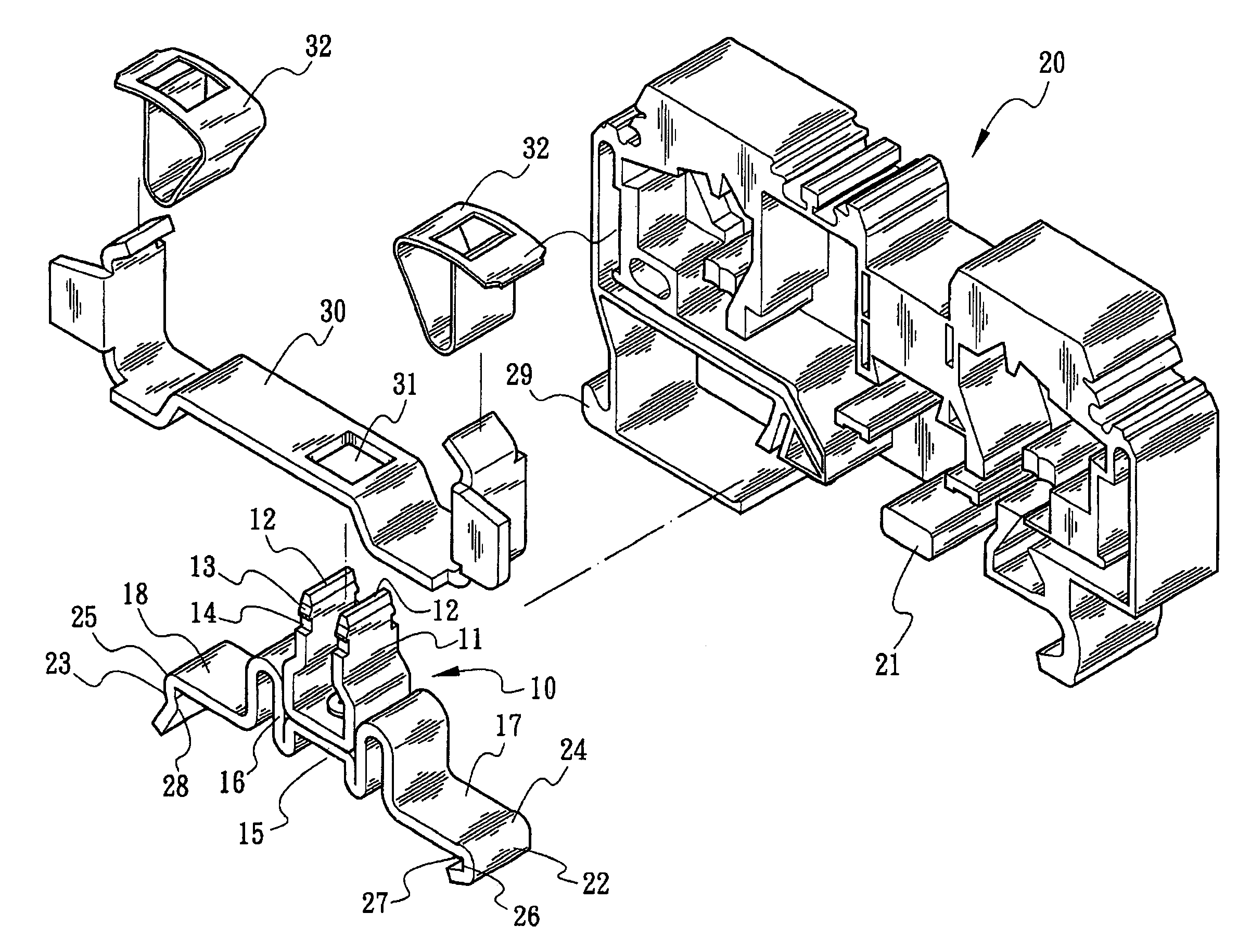
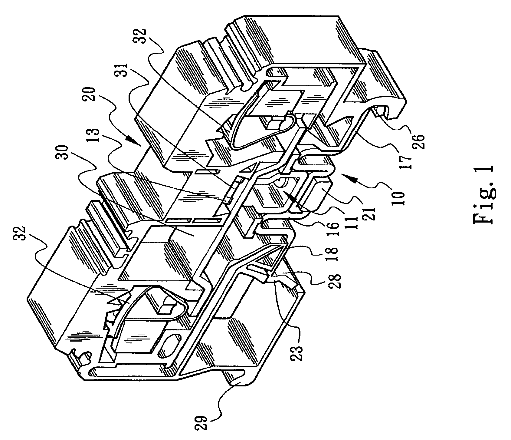
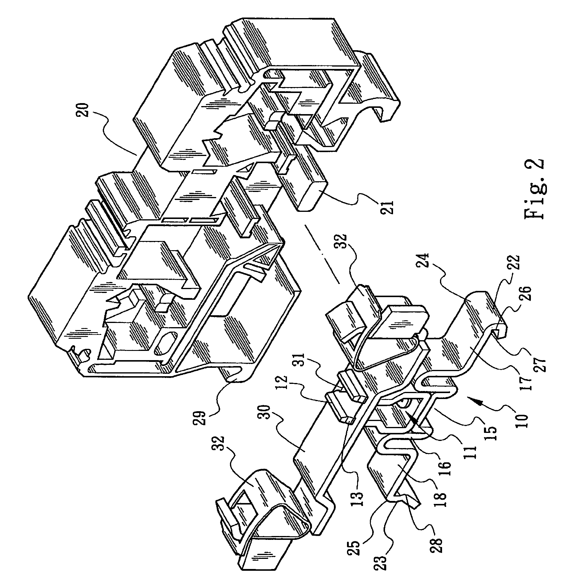
[0022]Please refer to FIGS. 1, 2 and 3. The rail-type grounding terminal structure of the present invention is composed of a metal grounding member 10 and an insulating housing 20. FIGS. 1, 2 and 3 show an internal structure of the insulating housing 20. The insulating housing 20 is generally made of plastic material. A leaf spring mount (or conductive board) 30 is installed in the housing 20. The leaf spring mount 30 is formed with a hole 31 and multiple wire connectors 32 for connecting with grounding wires 50 coming from a machine or an equipment (as shown in FIG. 9). The grounding member 10 is installed on the leaf spring mount 30. A first end 17 and a second end 18 of the grounding member 10 are latched on a conductive rail or grounding rail 40 (as shown in FIG. 9) to together form a grounding device.

[0023]Referring to FIGS. 4 and 5, the grounding member 10 is a substantially plate-shaped or bar-shaped member. In a preferred embodiment, the grounding member 10 is divided into t...


PUM


Abstract

A rail-type grounding terminal structure composed of a metal grounding member and an insulating housing. The amount of waste material produced in manufacturing of the grounding member is reduced. In addition, the grounding member has larger contact face to increase current value. Also, the grounding member can be easily tightly connected with a grounding rail. The grounding member is divided into two parts with predetermined configurations respectively. The grounding member includes a metal insertion leg mounted on a leaf spring mount and a bow section connected with the metal insertion leg. The bow section has a first end and a second end. The first and second ends outward extend and are latched on the grounding rail. The metal insertion leg has a head end, a slope and a shoulder section. The slope and the shoulder section are formed under the head end. The grounding terminal is operable to separate from or connect with the rail.

Description

BACKGROUND OF THE INVENTION[0001]The present invention is related to a rail-type grounding terminal structure composed of a metal grounding member and an insulating housing. The grounding member has such a configuration that the amount of waste material produced in manufacturing of the grounding member is reduced. In addition, the grounding member has larger contact face to increase current value. Also, a gap is defined between the grounding member and the insulating housing to provide an operation space.[0002]A conventional metal grounding terminal is enclosed in an insulating housing (generally made of plastic material). A row of such grounding terminals is latched on a grounding rail (or conductive rail) to establish a common grounding device for electric appliances or mechanical equipments. The grounding device serves to conduct and remove the voltage or static remaining in the machines. U.S. Pat. No. 5,362,259 discloses a typical ground conductor terminal.[0003]The ground condu...

Claims


Application Information

Patent Timeline
Patent Type & Authority Patents(United States)
IPC IPC(8): H01R13/648
CPCH01R4/64H01R9/2691H01R4/4827H01R4/48275
Inventor WU, CHIH-YUANHSU, BIAO-HUANGLEE, CHIEN-HSIN
Owner SWITCHLAB SHANGHAI
Why Eureka
Try Eureka