X-ray light valve based digital radiographic imaging systems

a digital radiographic imaging and light valve technology, applied in the field of radiographic imaging, can solve the problems of increasing the initial cost of the system, affecting the image quality of the imager,

Inactive Publication Date: 2010-03-30
SUNNYBROOK HEALTH SCI CENT
View PDF13 Cites 15 Cited by
  • Summary
  • Abstract
  • Description
  • Claims
  • Application Information

AI Technical Summary

Benefits of technology

[0010]According to one aspect of the present invention there is provided a radiographic digital imaging system based on a photoconductive detector and an electro-optic light modulator, referred to as x-ray light valve (XLV), which absorbs x-rays that have passed through an object to form an exposure of the object. The x-rays absorbed by the photoconductor create a static optical image, which is stored in the electro-optic light modulator, allowing the capture of the optical image to continue over a prolonged time. The stored optical image is subsequently digitized by an optical scanning device.
[0021]The present invention also provides advantages in the design, making it economically attractive. For example, by replacing the camera as used U.S. Pat. Nos. 6,052,432 and 5,847,499, and CA patent 2,228,325, with a scanning device, the complexity of the imager and hence the cost of the overall system is greatly reduced. The present invention requires little external circuitry beyond a high-voltage power supply and conventional computer technology. Therefore, the manufacturing costs can be kept very low. All elements of the overall design are chosen to be easily scalable to the sizes required for medical imaging without sacrificing resolution, pixel density, or the low cost of the overall system.

Problems solved by technology

These newer systems, while providing many advantages have considerably increased initial cost compared to older film based systems.
However, Active Matrix Flat Panel Imagers are extraordinarily expensive compared to the systems they are replacing and are capable of more than is needed for some applications, like radiography.
In order to modify a Computed Radiography system for immediate readout, the reader must be made very compact with a line scanning system as opposed to current spot scanning technology, which will increase the cost of the system significantly.
These systems have very poor image quality, requiring approximately four times as much radiation to achieve the same image quality as Active Matrix Flat Panel Imagers.
The reason for this drop in quality is the combination of the relatively poor x-ray absorption of Computed Radiography screens and the signal losses in the reader.
Other approaches exist for digital x-ray imaging but thus far none provides the quality of Active Matrix Flat Panel Imagers at a significant cost reduction.
However, generation of narrow x-ray beams is difficult and mounts significant costs.
This system is ultimately limited by the resolution of the camera system, and the signal loss between the screen and the camera.
However, this results in large amounts of noise.
Known prior art includes the apparatus described in references 1 to 3, U.S. Pat. Nos. 6,052,432 and 5,847,499, and CA patent 2,228,325; The suggested approach thus far suffers from problems characteristic for optically-demagnified screen-camera systems.
Although the image created is of high quality, and in some cases, can be acquired by the camera without significant loss of signal, the described configurations are only practical for small-area detectors.
The suggested implementations do not allow the imaging system to be scaled up to the size required for radiography without sacrificing pixel density, image quality or the overall cost.
Furthermore, the decay of the image in the electro-optical light modulator present in the devices disclosed in U.S. Pat. Nos. 6,052,432 and 5,847,499, and CA patent 2,228,325 and the acquisition of multiple images to improve the image quality or the dynamic range has been proven to be impractical thus far.
Those devices also suffer from the problems described above along with rapid image degradation due to the high ionic content of Polymer-Dispersed Liquid Crystals.

Method used


Image

  • X-ray light valve based digital radiographic imaging systems
  • X-ray light valve based digital radiographic imaging systems
  • X-ray light valve based digital radiographic imaging systems

Examples


Embodiment Construction

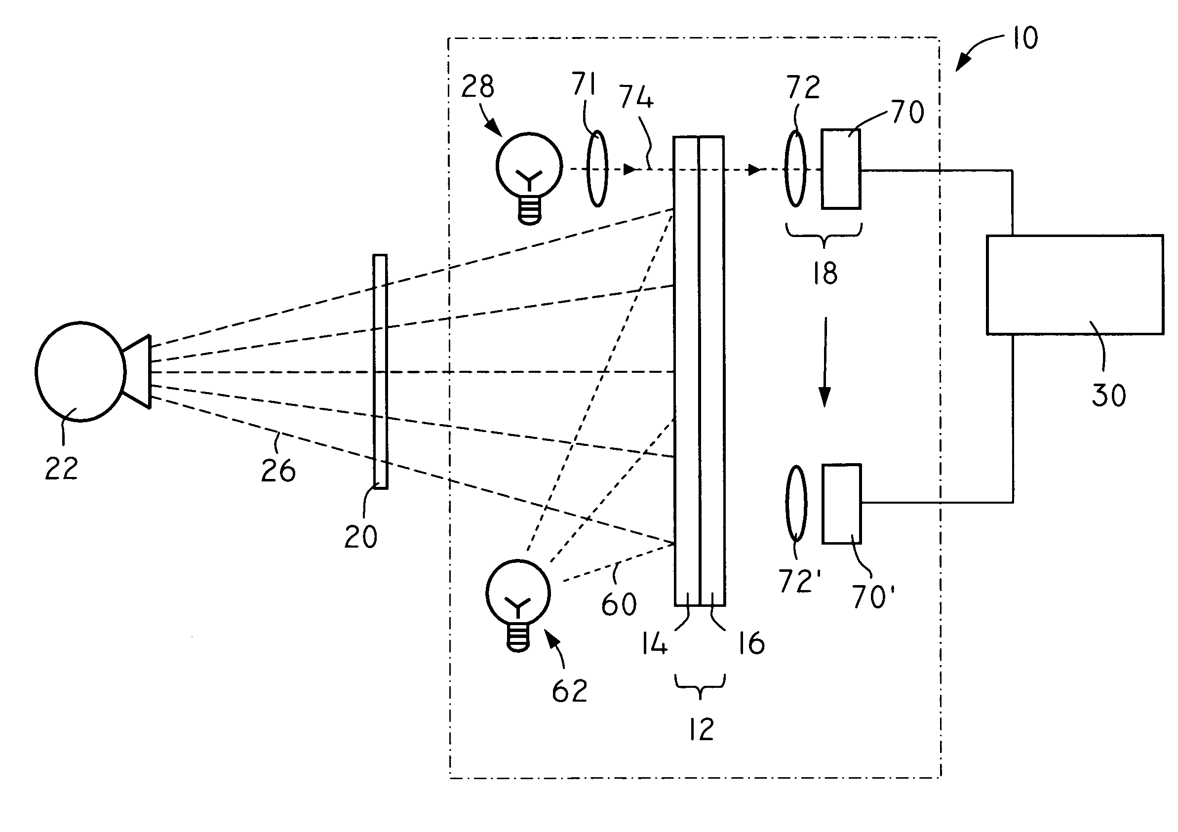
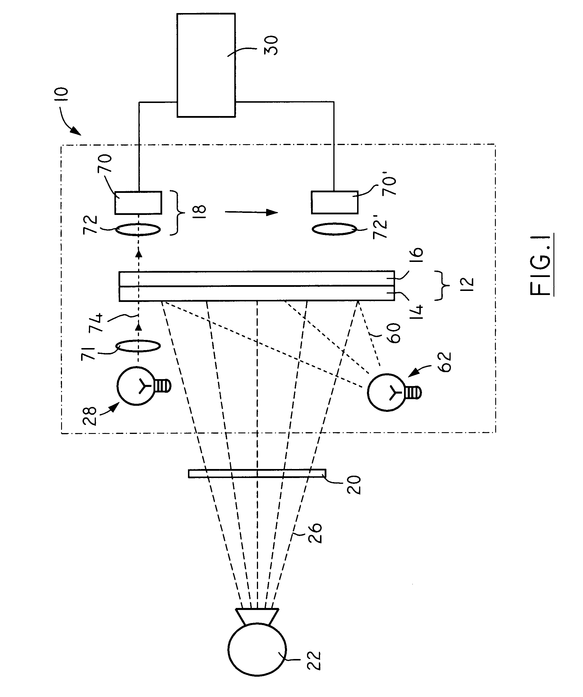
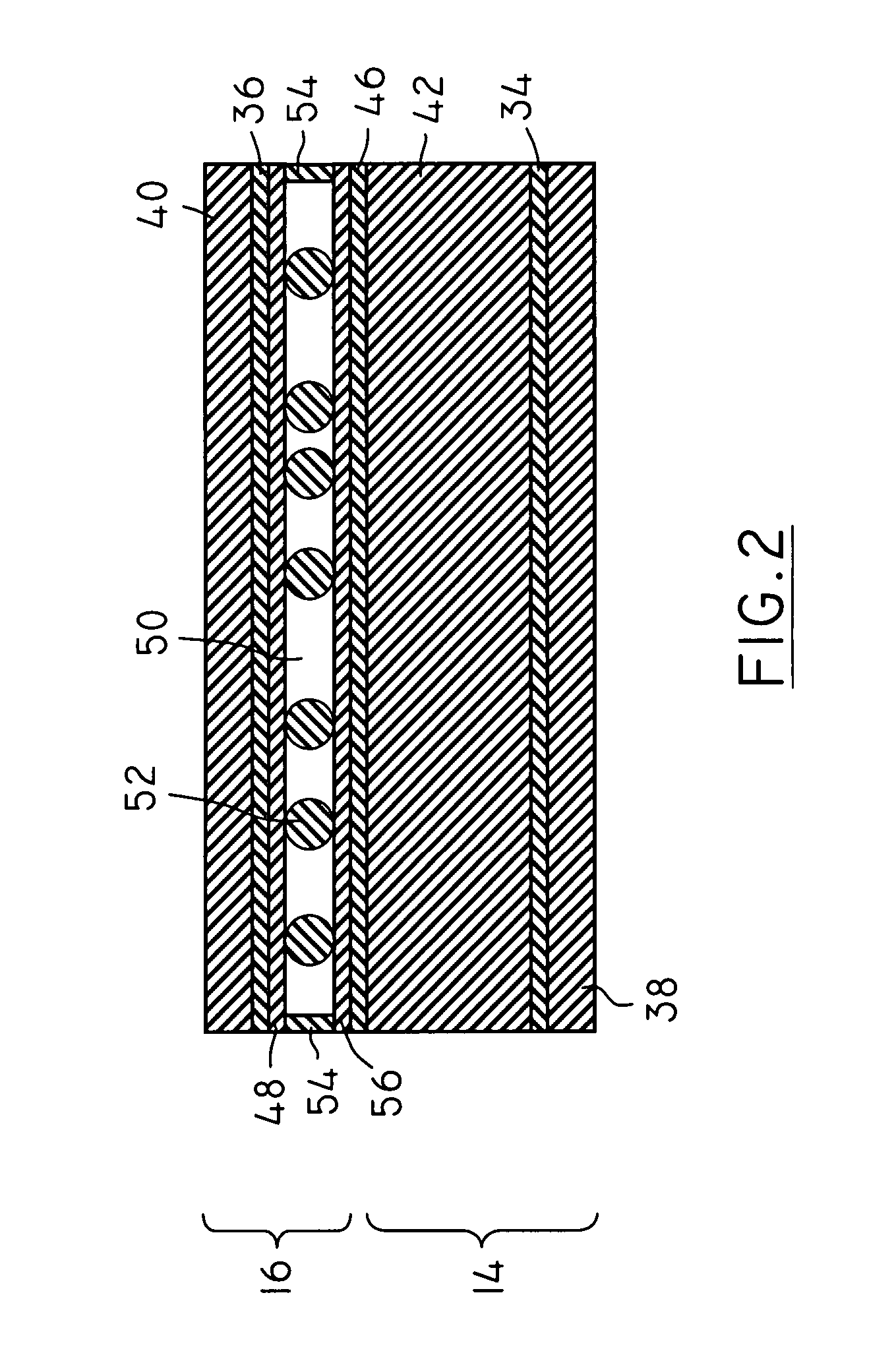
[0042]The systems described herein are directed, in general, to embodiments of digital radiographic imaging system. Although embodiments of the present invention are disclosed herein, the disclosed embodiments are merely exemplary and it should be understood that the invention relates to many alternative forms, including different shapes and sizes. Furthermore, the Figures are not drawn to scale and some features may be exaggerated or minimized to show details of particular features while related elements may have been eliminated to prevent obscuring novel aspects. Therefore, specific structural and functional details disclosed herein are not to be interpreted as limiting but merely as a basis for the claims and as a representative basis for enabling someone skilled in the art to employ the present invention in a variety of manner. For purposes of instruction and not limitation, the illustrated embodiments are all directed to embodiments of digital radiographic imaging systems.

[0043...


PUM


Abstract

The present invention provides a digital x-ray radiographic imaging system. The system is based on a photoconductive detector and an electro-optic light modulator, where the photoconductive detector layer absorbs x-rays that have passed through an object to form an exposure of the object. The absorbed x-rays create a static optical image, which is stored in the electro-optic light modulator, allowing the capture of the optical image to continue over longer time. The optical image is digitized using a scanning system and an external light source. The image is then processed and stored by a computer. After the optical image is recorded, an erasing mechanism is used to reset the system before a new exposure is made.

Description

CROSS REFERENCE TO RELATED U.S. PATENT APPLICATION[0001]This patent application relates to U.S. utility patent application Ser. No. 60 / 771,873 filed on Feb. 10, 2006 entitled X-RAY LIGHT VALVE BASED DIGITAL RADIOGRAPHIC IMAGING SYSTEMS, filed in English, which is incorporated herein in its entirety by reference.FIELD OF THE INVENTION[0002]This invention relates to radiation imaging and in particular to an x-ray imaging system and a method of x-ray imaging.BACKGROUND OF THE INVENTION[0003]Medical x-ray imaging systems up until recently were typically based on either film or phosphor. Newer systems based on large area flat panel technology or storage phosphors enabled production of digital x-ray images. These newer systems, while providing many advantages have considerably increased initial cost compared to older film based systems.[0004]Active Matrix Flat Panel Imagers are based on phosphor or photoconductor detectors with direct electronic readout of individual pixels. They can prov...

Claims


Application Information

Patent Timeline
Patent Type & Authority Patents(United States)
IPC IPC(8): H05G1/64
CPCG02F1/1354G01T1/246G01N2223/03G01N2223/50G02F2001/1352G02F1/1352
Inventor ROWLANDS, JOHN ALANWEBSTER, CHRISTIE ANNKOPRINAROV, IVAYLOOAKHAM, PETERGERMANN, STEPHENSTILES, JAMES ALEXANDER ROBERT
Owner SUNNYBROOK HEALTH SCI CENT
Why Eureka
Try Eureka