High speed generator rotor design incorporating positively restrained balance rings

a positive restraint, high-speed technology, applied in the field of generators, can solve the problems of unbalanced rotor, complex manufacture and maintenance, and the inability to add balance weights over the complete 360 degree of the balance plan

Inactive Publication Date: 2010-03-30
HONEYWELL INT INC
View PDF12 Cites 7 Cited by
  • Summary
  • Abstract
  • Description
  • Claims
  • Application Information

AI Technical Summary

Problems solved by technology

As the rotor band, the interpole wedges, and the band supports are all individual pieces, manufacture and maintenance may be complex.
At a high rate of speed, such position changes can result in an unbalanced rotor.
Thus, “dead spots” exist where it may be impossible to add balance weights over the complete 360 degrees of the balance plane.

Method used


Image

  • High speed generator rotor design incorporating positively restrained balance rings
  • High speed generator rotor design incorporating positively restrained balance rings
  • High speed generator rotor design incorporating positively restrained balance rings

Examples


Embodiment Construction

[0020]The following detailed description is of the best currently contemplated modes of carrying out the invention. The description is not to be taken in a limiting sense, but is made merely for the purpose of illustrating the general principles of the invention, since the scope of the invention is best defined by the appended claims.

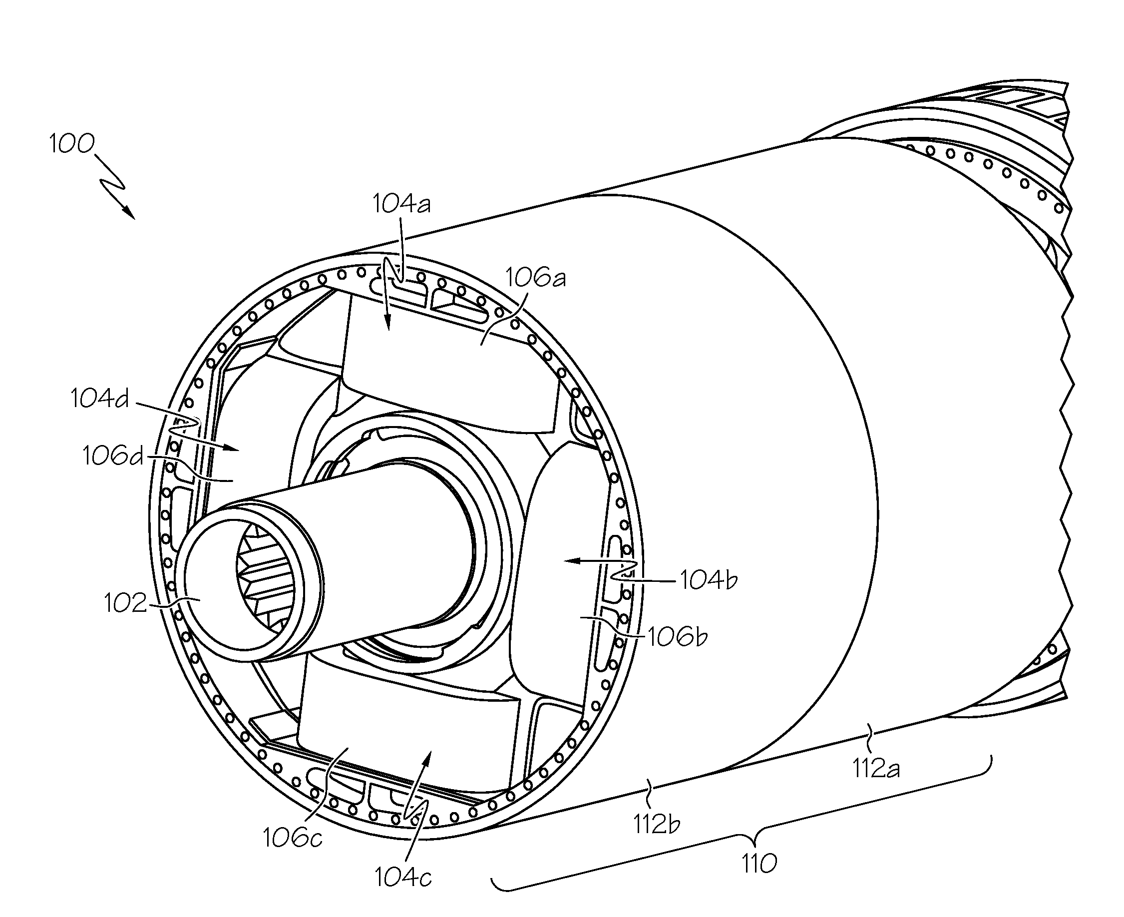
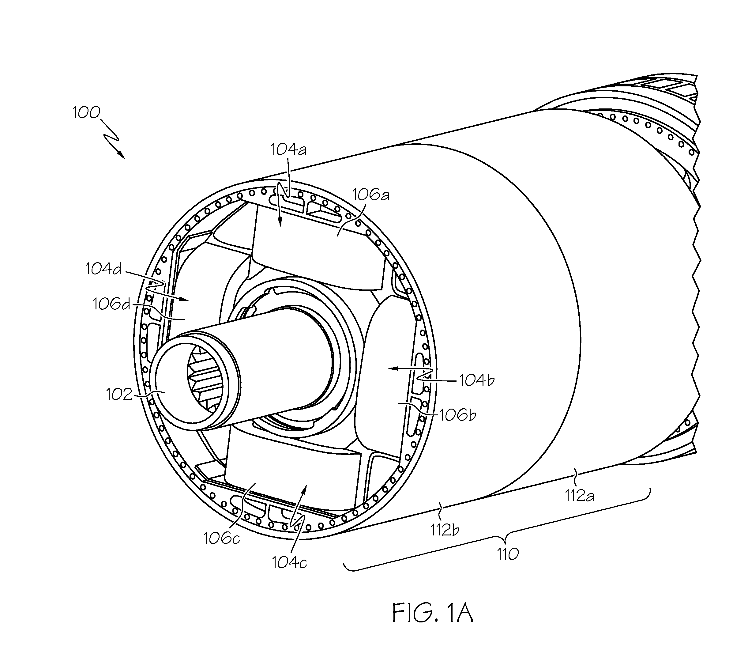
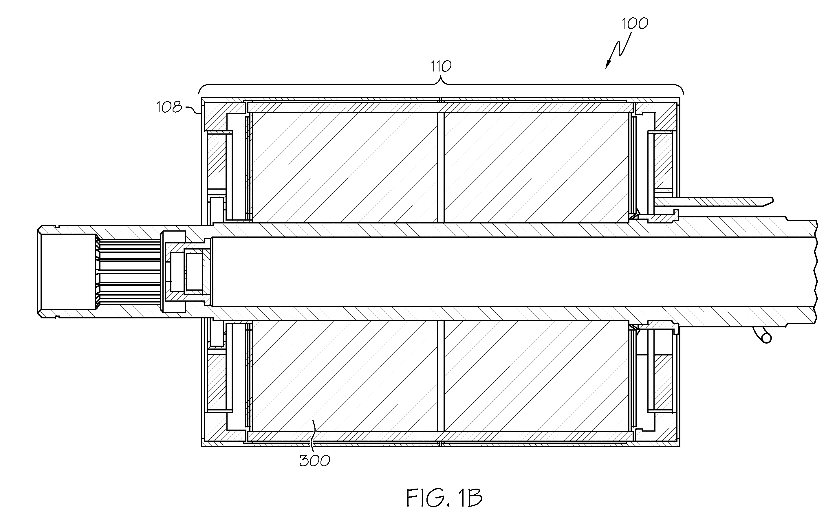
[0021]Broadly, embodiments of the present invention may include a balance ring that may be used in an electric generator. Embodiments of the present invention may include a rotor can (or sleeve) over a rotor core and extending beyond the end of the rotor core. The balance ring may function as a rotor band and as rotor band supports providing radial support for coil end turns. The balance ring may include a series of holes (or balancer) to balance a rotor of the generator. The balance ring may be located within a portion of the rotor can extending beyond the end of the rotor core. Thereby, the balance ring may be positively restrained in the rotor can. E...


PUM

PropertyMeasurementUnit
diameteraaaaaaaaaa
lengthaaaaaaaaaa
weightaaaaaaaaaa

Abstract

A generator may incorporate a positively restrained balance ring. A generator may include a rotor core including a rotor, and a balance ring. The balance ring may include a weight. The balancer may include a plurality of balance holes in the ring, at least one of the plurality of balance holes to receive a weighted insert. A method of balancing a rotor of a generator may include mounting a balance ring adjacent to a rotor core, and adjusting weights to be located at one or more of a plurality of positions equally spaced around the balance ring to balance the rotor.

Description

BACKGROUND OF THE INVENTION[0001]Embodiments of the present invention relate generally to generators and, more particularly, to high speed generators incorporating positively restrained balance rings.[0002]There is a trend of utilizing more and more electric systems in vehicles such as aircraft. This is due in part to a change over from traditionally non-electric systems, such as hydraulic systems, to electric systems. This trend is also due to the creation of entirely new electric systems that did not exist in the past. Examples include replacing hydraulic actuators with electric motors and the removal of bleed air from cabin pressurization. Consequently, demand for electric power in vehicles continues to increase.[0003]Typically, electric power is generated in a vehicle by one or more electric generators. Due to the increasing power requirements, generators are being run at higher speeds. Such generators may be referred to as “high-speed” generators. Conventional high-speed genera...

Claims


Application Information

Patent Timeline
Patent Type & Authority Patents(United States)
IPC IPC(8): H02K5/24
CPCH02K1/24H02K15/165H02K7/04Y10T29/49012
Inventor WADDELL, SIMON L.MCDOWALL, GREGORSCHERZINGER, WILLIAM M.
Owner HONEYWELL INT INC
Why Eureka
Try Eureka