Shake correction device, filming device, moving image display device, shake correction method and recording medium

a technology of shake correction and shake device, which is applied in the field of shake correction device, filming device, moving image display device, shake correction method and recording medium, can solve the problems of increasing the cost of the device and reducing the reduction of image quality, and achieve the effect of simple process

Inactive Publication Date: 2010-03-30
NVIDIA CORP
View PDF14 Cites 3 Cited by
  • Summary
  • Abstract
  • Description
  • Claims
  • Application Information

AI Technical Summary

Benefits of technology

[0007]An object of the invention is to provide a shake correction device, a filming device, a moving image display device, a shake correction method and a recording medium which can correct a shake, by a simple process, even in the event that a frame sampling rate is high.
[0020]According to the configuration, since the frames with no shake are selected simply by comparing the angular velocity of the frame and the angular velocity tolerance range, it is possible to quickly and easily configure the moving image with only frames with no shake.
[0024]According to the configuration, since the frames with no shake are selected simply by comparing the angular velocity of the frame and the angular velocity tolerance range, it is possible to quickly and easily select and display only the frames with no shake.
[0036]According to the configuration, as each of the X axis angular velocity, the Y axis angular velocity and the Z axis angular velocity are detected, it is possible to more accurately detect shake occurring in the frame.
[0038]According to the configuration, as the information on the sampled angular velocity is stored, at the time of the next sampling, by referring to the history, it is possible to increase the accuracy of a shake tendency determination.
[0041]According to the configuration, as the frames with no shake are selected simply by comparing the angular velocity of the frame and the angular velocity tolerance range, it is possible to quickly and easily display the moving image with only the frames with no shake.

Problems solved by technology

Also, in a camera which films a motionless image, a shake reduction camera which has a shake detector such as, for example, an acceleration sensor, and reduces a reduction in image quality due to a distortion of images using detected shake information, has been known.
However, there is a problem in that, at the time of the moving image reproduction display, it is necessary to carry out a hand shake amount calculation process, a display subject area movement process and a display subject area extraction process, or a shake prediction process, for every frame.
Consequently, in the event that the frame sampling rate when filming is high, it is necessary for the filming device to include a sophisticated and high-speed processor in order to carry but all of the processes for every frame at the time of the moving image reproduction display, the cost of the device increases.
Furthermore, a display subject area movement process and a display subject area extraction process for each frame, as in a heretofore known technology, are unnecessary, even in the event that the sampling rate of the frames is high.

Method used


Image

  • Shake correction device, filming device, moving image display device, shake correction method and recording medium
  • Shake correction device, filming device, moving image display device, shake correction method and recording medium
  • Shake correction device, filming device, moving image display device, shake correction method and recording medium

Examples


first embodiment

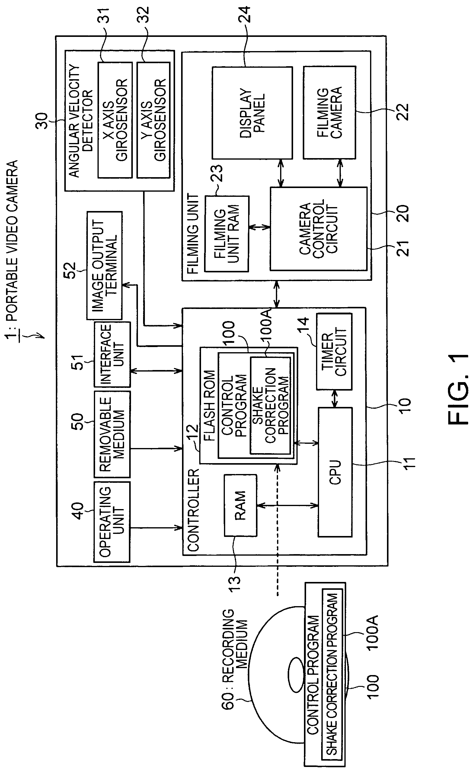
[0063]FIG. 1 is a block diagram showing a configuration of a portable digital video camera (hereafter called a “portable video camera”) 1 according to the embodiment. As shown in FIG. 1, the portable video camera 1 includes a controller 10, a filming unit 20, an angular velocity detector (a shake detector) 30, an operating unit 40, a removable medium 50, an interface unit 51 and an image output terminal 52.

[0064]The controller 10, controls each portion of the portable video camera 1 and includes a CPU 11 which executes various programs, a rewritable flash ROM (hereafter called simply an “ROM”) 12 which stores a control program 100, executed by the CPU 11, and various data, a RAM 13 which temporarily stores a calculation result of the CPU 11 and various data, and a timer circuit 14 which counts time.

[0065]A shake correction program 100A is included in the control program 100 stored in the ROM 12. The controller 10 executes the shake correction program 100A at a time of a moving image...

second embodiment

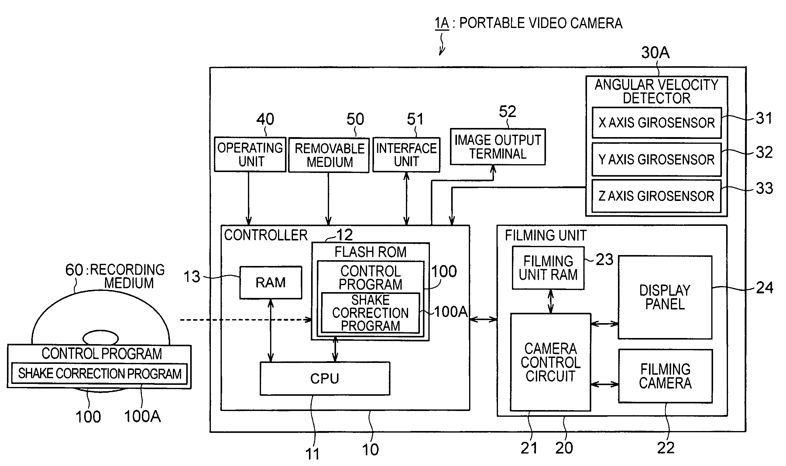
[0117]In the first embodiment, the frame selected at the time of the moving image reproduction display was determined based on the reference frame position A1 and the hand shake tolerance range C. In contrast, in a second embodiment, a description will be given of a portable video camera 1A which determines the hand shake tolerance ranges C in accordance with a tendency of the user's hand shake.

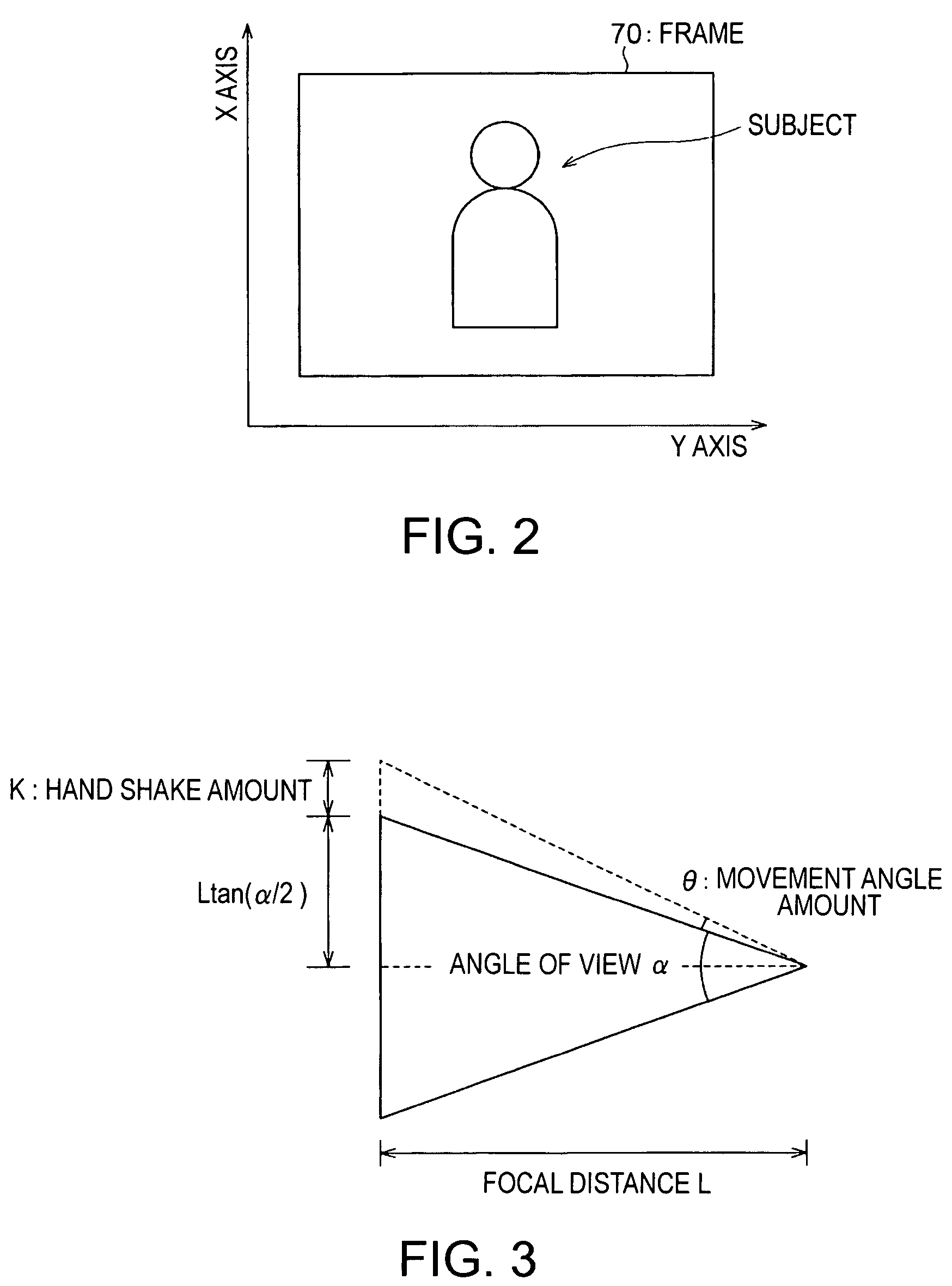
[0118]FIG. 9 is a block diagram showing a configuration of the portable video camera 1A according to the embodiment. As, shown in the figure, the portable video camera 1A includes an angular velocity detector 30A which has, in addition to the X axis gyrosensor 31 and the Y axis gyrosensor 32, a Z axis gyrosensor 33. The Z axis gyrosensor 33 detects an angular velocity ωz which accompanies a movement in a direction perpendicular to an X-Y axis (hereafter defined as a Z axis) shown in the previously described FIG. 2, and transmits an angular velocity detection signal of a voltage value correspo...


PUM


Abstract

A filming device includes a filming unit which imports a plurality of frames configuring a moving image at a prescribed sampling rate, a shake amount detection unit which detects a shake amount of each of the frames, a frame position calculation unit which calculates a frame position of each frame based on the shake amount, a reference frame position determination unit which determines a reference frame position to be a reference of a display subject frame, and a frame selection and transmission unit which selects and sequentially transmits frames positioned within a prescribed range centered on the reference frame position.

Description

BACKGROUND[0001]1. Technical Field[0002]The present invention relates to a technique for correcting the unsteadiness or shaking of a moving image filmed by hand through a portable video camera or the like.[0003]2. Description of the Related Art[0004]A hand shake correction function for correcting hand shake in a filming device such as a portable digital video camera or a digital camera with a moving image filming function is known. In addition to importing frames at a prescribed sampling rate, this type of filming device, clips images of a display subject area of a fixed area from each frame and sequentially displays them. When the filming device corrects the hand shake, it calculates, for every frame, a direction and a size of a shake of an image caused by the hand shake as a hand shake amount, and relatively moves the display subject area within the frame based on the hand shake amount, so that the display subject area is fixed regardless of the hand shake. As a result, as the fil...

Claims


Application Information

Patent Timeline
Patent Type & Authority Patents(United States)
IPC IPC(8): H04N5/228
CPCH04N5/23248H04N23/68
Inventor NOMURA, KAZUOSANO, MEGUMINAGAISHI, MICHIHIROHOSODA, TATSUYA
Owner NVIDIA CORP
Why Eureka
Try Eureka