Technique for reducing wasted material on a printed circuit board panel

a technology of printed circuit board and waste material, which is applied in the direction of printed circuit parts, metal working apparatus, manufacturing tools, etc., can solve the problems of the difficulty of packaging the pcbs and the discrete components into the electronic device housing, and the cost of manufacturing a rigid-flex pcb can be several times higher than the cost of manufacturing a rigid pcb, so as to achieve the effect of substantially reducing the amount of wasted spa

Inactive Publication Date: 2010-04-06
APPLE INC
View PDF9 Cites 9 Cited by
  • Summary
  • Abstract
  • Description
  • Claims
  • Application Information

AI Technical Summary

Benefits of technology

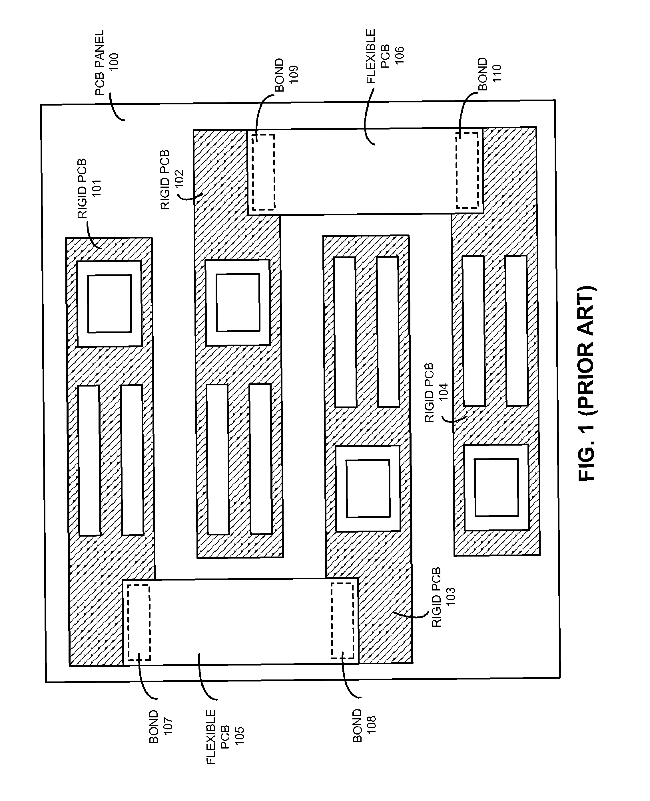
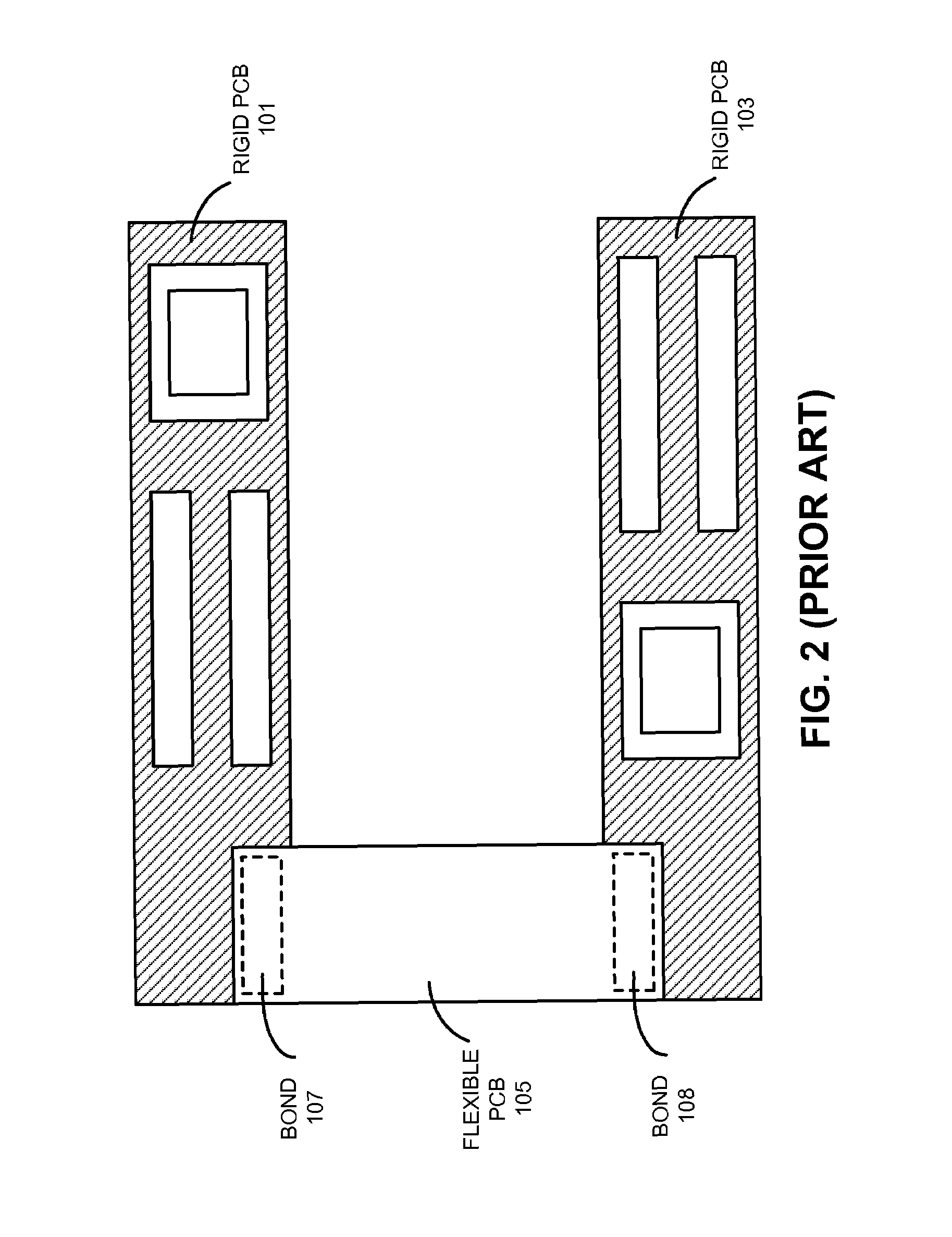
[0010]In some embodiments, layouts for rigid-flex PCBs that are to be coupled to each can be severed at specified points so that the severed rigid-flex PCBs can be arranged on a PCB panel so that the amount of wasted space is substantially minimized. In some embodiments, after the layouts of the rigid-flex PCBs are severed, the layouts are further modified so that bond regions are created. These bond regions can be used to recouple the rigid-flex PCBs to each other.

Problems solved by technology

As a result, the process of packaging the PCBs and the discrete components into a housing for the electronic device becomes more difficult.
Unfortunately, the cost of manufacturing a rigid-flex PCB can be several times higher than the cost of manufacturing a rigid PCB.
This extra cost is typically a function of the complexity of the manufacturing process (e.g., the number of machines and processing steps in the manufacturing process) and the amount of wasted space on the PCB panel.

Method used


Image

  • Technique for reducing wasted material on a printed circuit board panel
  • Technique for reducing wasted material on a printed circuit board panel
  • Technique for reducing wasted material on a printed circuit board panel

Examples


Embodiment Construction

[0024]The following description is presented to enable any person skilled in the art to make and use the invention, and is provided in the context of a particular application and its requirements. Various modifications to the disclosed embodiments will be readily apparent to those skilled in the art, and the general principles defined herein may be applied to other embodiments and applications without departing from the spirit and scope of the present invention. Thus, the present invention is not limited to the embodiments shown, but is to be accorded the widest scope consistent with the principles and features disclosed herein.

[0025]The data structures and code described in this detailed description are typically stored on a computer-readable storage medium, which may be any device or medium that can store code and / or data for use by a computer system. The computer-readable storage medium includes, but is not limited to, volatile memory, non-volatile memory, magnetic and optical st...


PUM

PropertyMeasurementUnit
flexibleaaaaaaaaaa
pressureaaaaaaaaaa
temperatureaaaaaaaaaa

Abstract

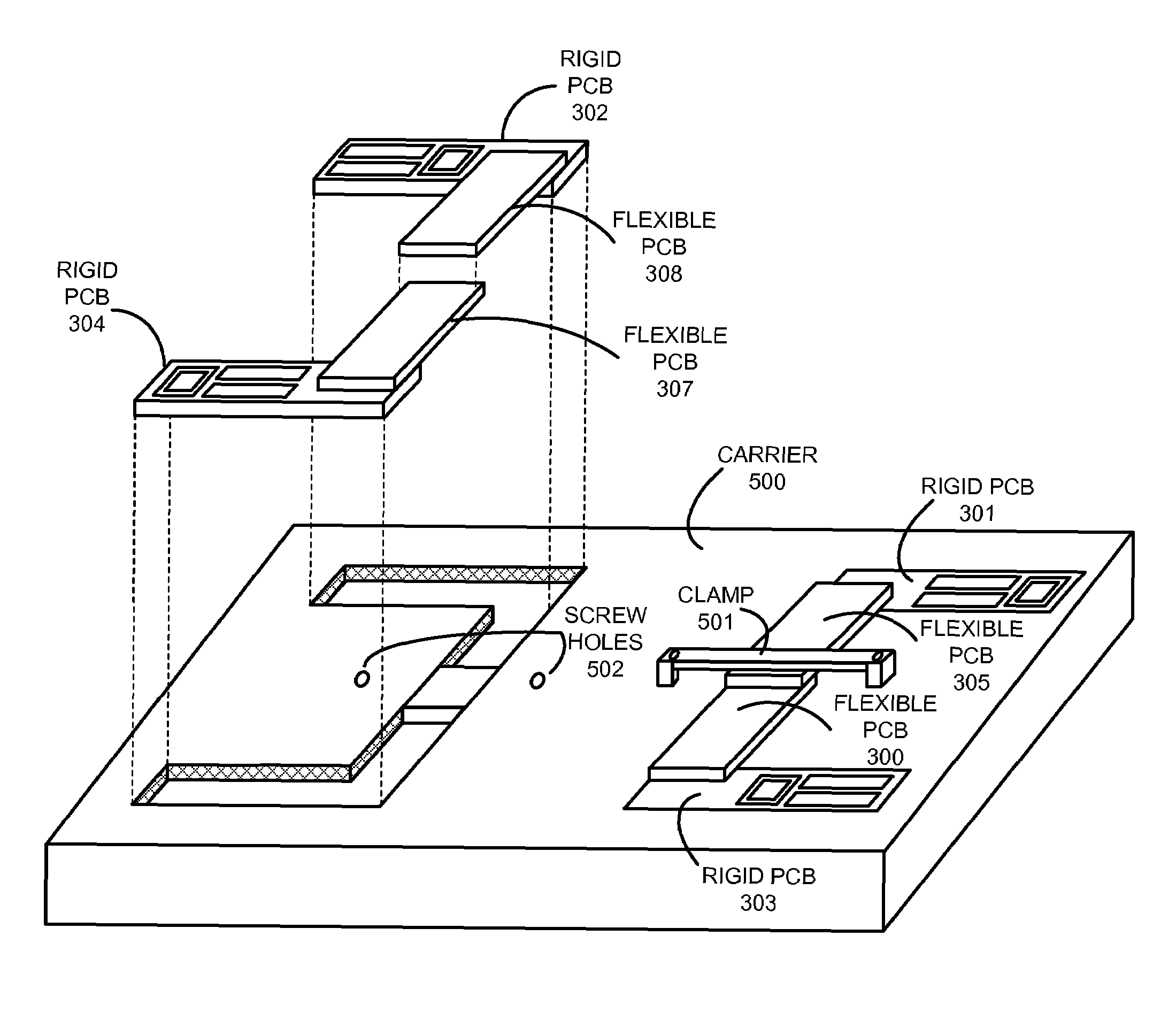
A process for assembling a rigid-flex printed circuit board (PCB) is presented. During operation, the process receives rigid-flex PCBs that are to be coupled together, wherein a rigid-flex PCB includes flexible PCBs coupled to rigid PCBs. The process then places the PCBs onto a carrier which is configured to: align the PCBs so that bond regions located on the flexible PCBs overlap with bond regions located on corresponding flexible PCBs, and apply pressure to the overlapped bond regions. The process then sends the carrier through a reflow oven which reflows solder on the PCBs so that the components become mechanically and electrically coupled to the PCBs. The temperature profile generated by the reflow oven and the pressure applied by the carrier cures and sets an anisotropic conductive film located in the bond regions so that the overlapped flexible PCBs become mechanically and electrically coupled together.

Description

RELATED APPLICATION[0001]This application hereby claims priority under 35 U.S.C. §119 to U.S. Provisional Patent Application No. 61 / 030,079 filed 20 Feb. 2008, entitled “TECHNIQUE FOR REDUCING WASTED MATERIAL ON A PRINTED CIRCUIT BOARD PANEL,” by inventors Michael N. Rosenblatt and Amir Salehi.BACKGROUND[0002]1. Field of the Invention[0003]The present invention relates to techniques for manufacturing printed circuit boards (PCBs). More specifically, the present invention relates to a method and apparatus for reducing wasted material during the process of manufacturing a PCB panel.[0004]2. Related Art[0005]Electronic devices typically include integrated circuit (IC) chips and other discrete electronic components which are mounted onto one or more printed circuit boards (PCBs). These electronic devices can also include other discrete components, such as a display or a battery, which are not mounted onto PCBs. The PCBs and the other discrete components are then assembled into a housing...

Claims


Application Information

Patent Timeline
Patent Type & Authority Patents(United States)
IPC IPC(8): H05K3/36H01R12/00H05K1/00H05K1/03H05K3/00H05K3/30H05K3/34
CPCH05K1/148H05K3/361Y10T29/49126H05K3/007H05K3/323H05K3/341H05K3/3494H05K2201/058H05K2201/10393H05K2203/0152Y10T29/49124Y10T29/53265Y10T29/49144Y10T29/49117Y10T29/53174Y10T29/5313Y10T29/49133H05K3/0052
Inventor ROSENBLATT, MICHAEL N.SALEHI, AMIR
Owner APPLE INC
Why Eureka
Try Eureka