
Position adjustment mechanism

a technology of positioning adjustment and adjustment mechanism, which is applied in the direction of machine supports, adjustable height tables, domestic objects, etc., can solve the problems of affecting the stability of the bearing, the failure of the bearing, and the difficulty of adjusting the position, so as to improve stability and solidity.

Inactive Publication Date: 2010-04-06
HALSTEAD ROGER GEOFFREY
View PDF3 Cites 2 Cited by
  • Summary
  • Abstract
  • Description
  • Claims
  • Application Information

AI Technical Summary

Benefits of technology

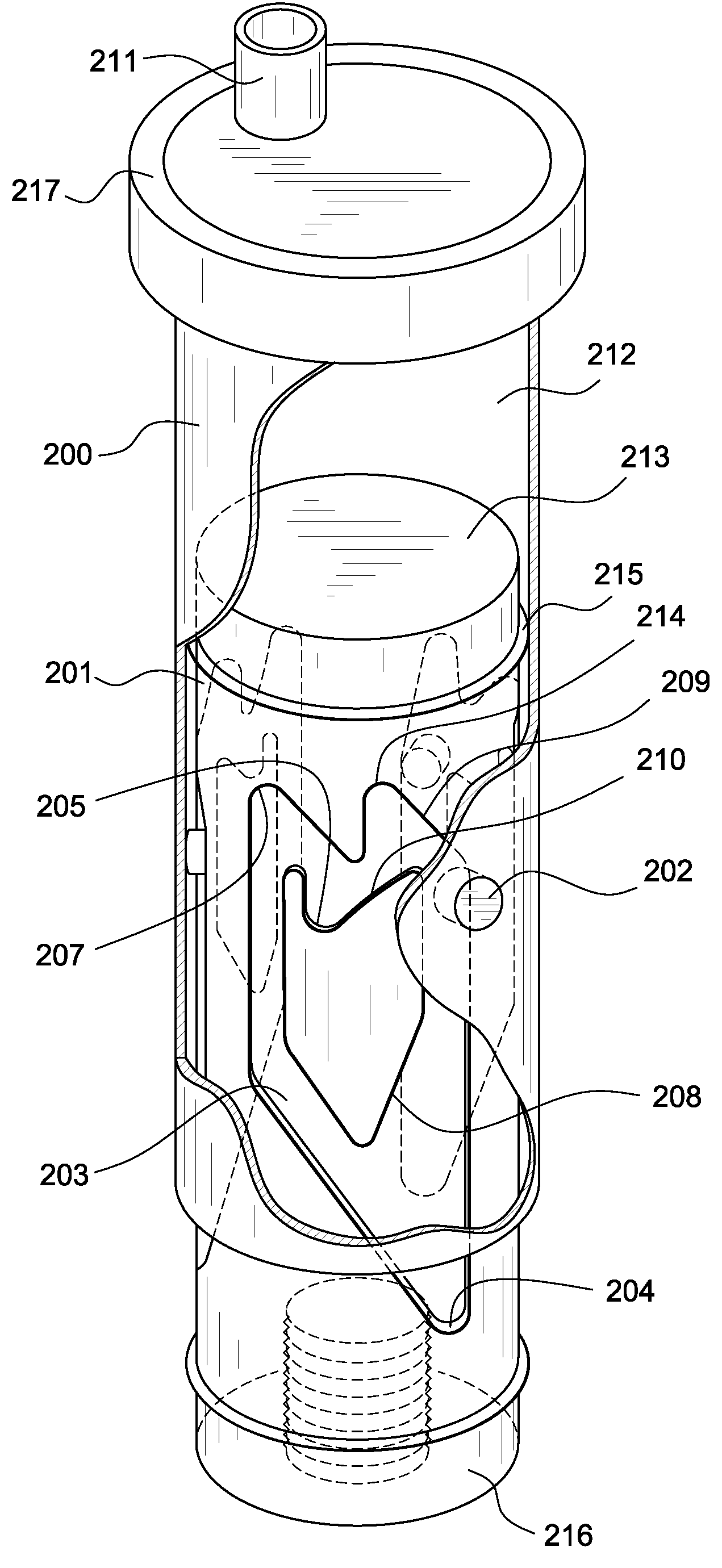
[0013]According to the invention, there is provided a position adjustment mechanism, the mechanism comprising: —two cylindrical portions, a first one of the portions being slidably disposed inside a second one of the portions, wherein one of the portions has at least three detents and the other portion has at least three members for engaging in respective the detents to hold the portions in a first position, the members being removable from the detents to allow the portions to move into a second position; wherein the detents and members are equi-spaced around the first and second portions. Having three such equi-spaced detents and members affords enhanced stability and solidity. In this regard, being equi-spaced, the detents and members are provided at substantially 120° intervals around the circumference of the portions and hence are not diametrically opposite one another. This avoids the possibility that the members will effectively form an axle about which the portions would tend to rock in relation to one another.
[0015]Preferably, the portions are biassed away from each other by a resilient device. The use of cylindrical portions allows the provision of such a resilient device-positioned between the portions. These resilient device tend to urge the positions apart, and this helps prevent the mechanism from jamming.
[0019]It is further preferred for there to be an odd number of grooves, and a corresponding number of members, greater than one. This reduces the chance of the mechanism jamming.
[0020]Preferably, one of the portions is in contact with a first body and the other of the portions is in contact with a second body, with motion of the portions between the first position and the second position serving to adjust the vertical distance between the bodies.
[0024]With such an arrangement, the need to manually lift an object being supported by the apparatus is avoided. Preferably, the first and second elements comprise respective first and second cylindrical portions, the first one of which is disposed inside the second. In this manner, the first and second cylindrical portions can function as a piston / cylinder arrangement.

Problems solved by technology

Moreover, where only a single detent and member is provided, there is a greater possibility that the cylindrical portions will be misaligned, such that excess forces are exerted on the member causing it to shear.
Providing two detents and members also can be problematic as indicated above, since if one of the cylindrical portions has rocked to one side it will be misaligned and forces on the two members will not be equally shared.
This can lead to the one bearing the excess forces failing, following which the remaining one will fail.

Method used


Image

  • Position adjustment mechanism
  • Position adjustment mechanism
  • Position adjustment mechanism

Examples


Embodiment Construction

[0036]As shown in FIG. 2, the preferred embodiment of the height adjustment mechanism 10 comprises two main parts, a first portion 12, which in this embodiment has a foot 18 for engaging a floor, and a second portion 50 for connection to a snooker or pool table.

[0037]The first portion 12 comprises two parts, a floor-engaging part 14 shown in FIG. 3a and a grooved member shown in FIG. 3b.

[0038]The floor-engaging part comprises a foot 18 for resting on the floor, and a threaded rod 20 extending upwardly from the center of the foot.

[0039]The grooved member is in the form of a cylinder 22, with a threaded bore formed 24 in its lower face. The threaded rod 20 engages in the threaded bore 24, and the rod can be screwed into and out of the bore for fine adjustment purposes.

[0040]In addition, the central region of the cylinder 22 has an upwardly-open hollow 26 therein to accommodate a spring, which will be described in more detail later.

[0041]A groove 28 is machined into the outer cylindri...


PUM


Abstract

The present invention relates to a position adjustment mechanism, comprising two cylindrical portions, a first one of the portions being slidably disposed inside a second one of the portions. One of the portions has at least three detents and the other portion has at least three members for engaging in respective the detents to hold the portions in a first position, the members being removable from the detents to allow the portions to move into a second position; wherein the detents and members are equi-spaced around the first and second portions.

Description

[0001]This application is a continuation-in-part of PCT / GB02 / 04175 filed 13 Sep. 2002.BACKGROUND OF THE INVENTION[0002]The present invention relates to a position adjustment mechanism, and more particularly to an adjustment mechanism for use in raising and lowering the height of the bed of a snooker table, billiards table, pool table or the like.[0003]Snooker tables, and tables for playing related games such as billiards and pool, are of course well known. Such tables can be used as dining tables, by resting a cover on the cushions of the table, but the dining table formed by doing this is generally not at a convenient height for dining, as the surface of the dining table is normally too high. The height difference is normally around 75 mm (3 inches).BRIEF DESCRIPTION OF THE PRIOR ART[0004]Mechanisms are known for adjusting the height of the surface of the table, thus allowing the table to used both as a snooker table (or a billiards or pool table) and as a dining table. When it is ...

Claims


Application Information

Patent Timeline
Patent Type & Authority Patents(United States)
IPC IPC(8): F16M13/00A47B9/00A47B91/02
CPCA47B91/024A47B9/00
Inventor HALSTEAD
Owner HALSTEAD ROGER GEOFFREY
Learn More