

Self-resetting paddle target
a self-reset and paddle target technology, applied in the field of targets, can solve the problem that the prior art has not developed a self-reset paddle targ
- Summary
- Abstract
- Description
- Claims
- Application Information
AI Technical Summary
Benefits of technology
Problems solved by technology
Method used
Image

Examples
Embodiment Construction
[0031]While the present invention is susceptible of embodiment in various forms, there is shown in the drawings and will hereinafter be described a presently preferred embodiment with the understanding that the present disclosure is to be considered an exemplification of the invention and is not intended to limit the invention to the specific embodiment illustrated.
[0032]It should be further understood that the title of this section of this specification, namely, “Detailed Description of the Invention,” relates to a requirement of the United States Patent Office, and does not imply, nor should be inferred to limit the subject matter disclosed herein.
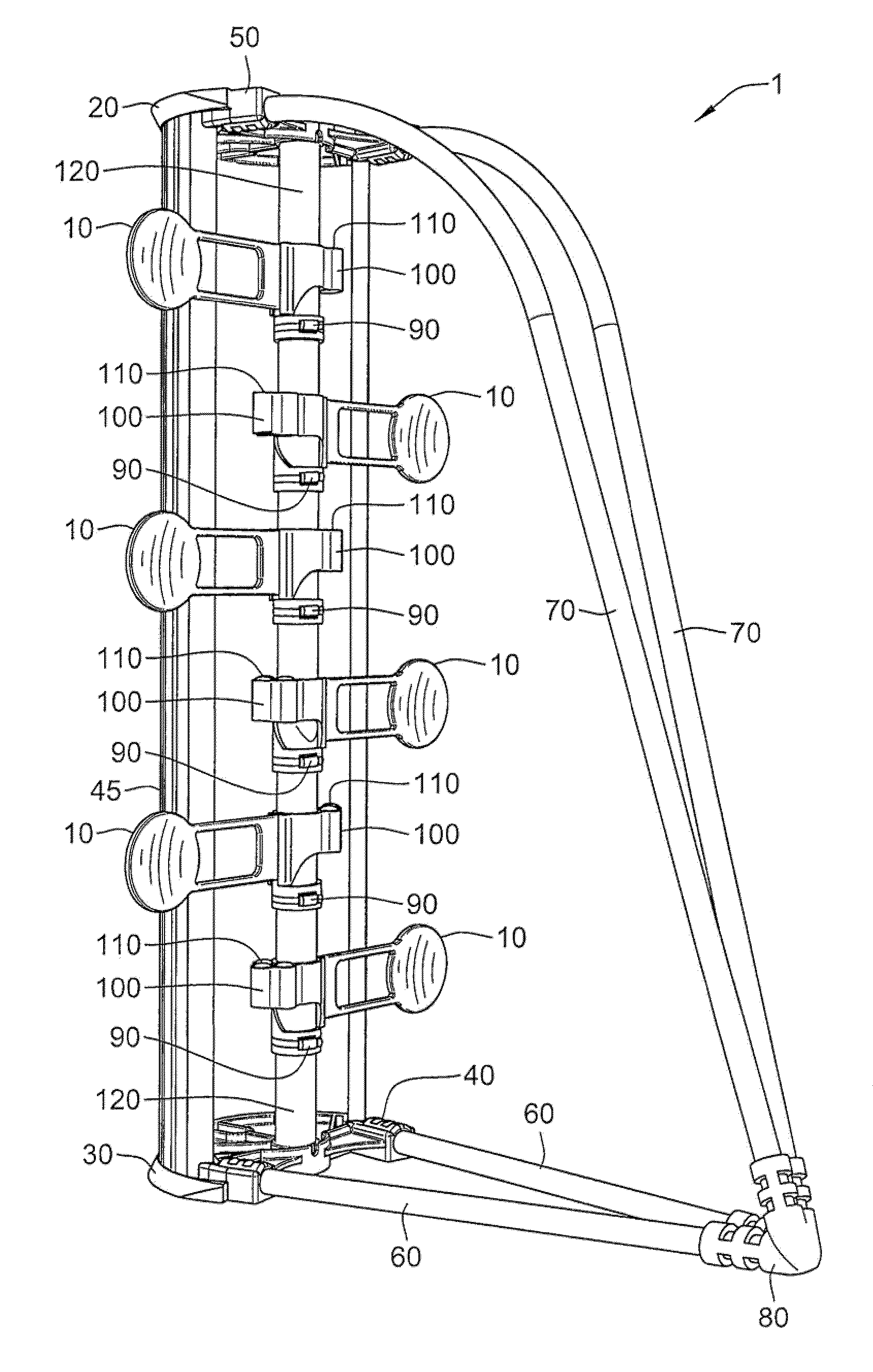
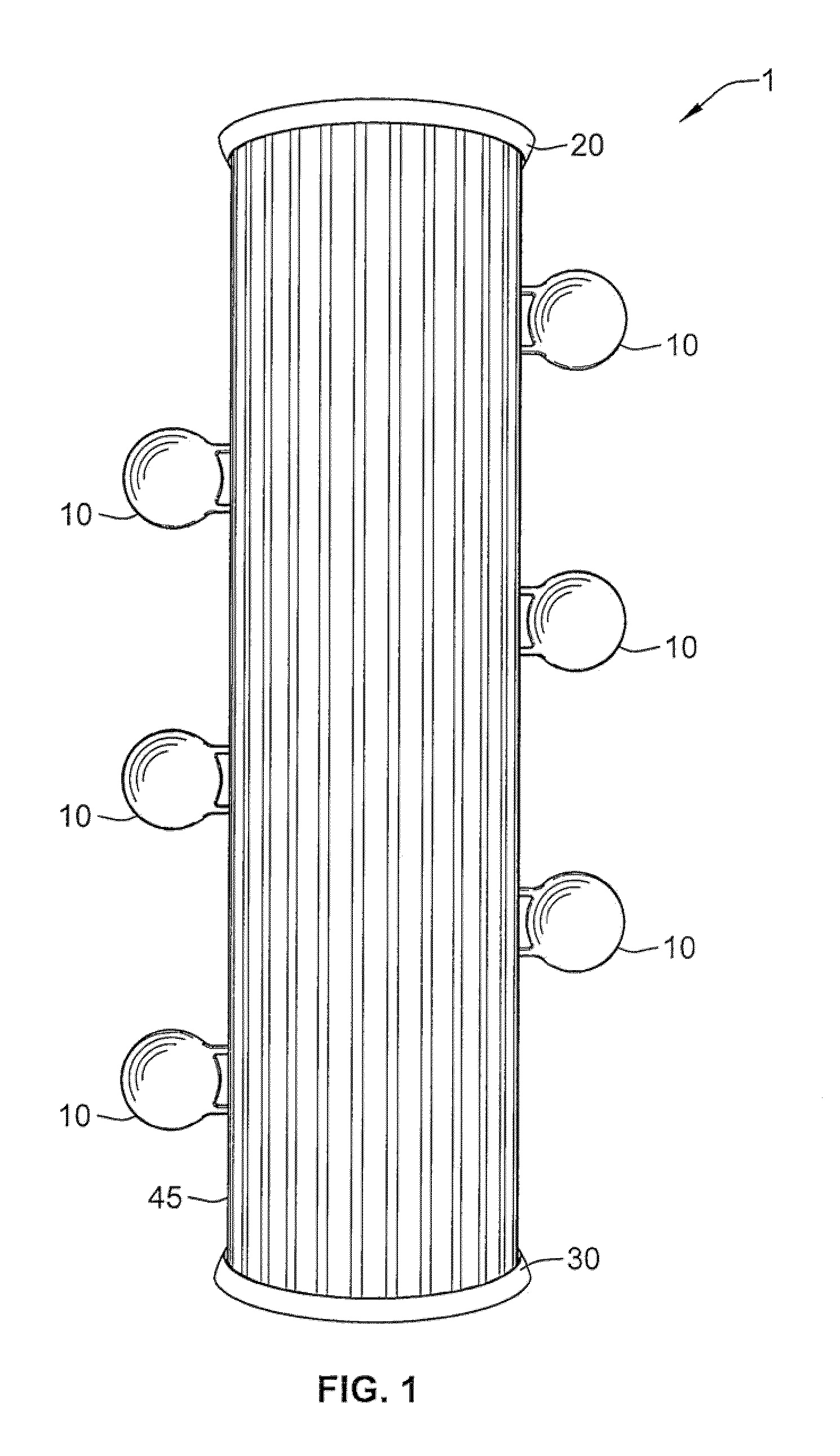
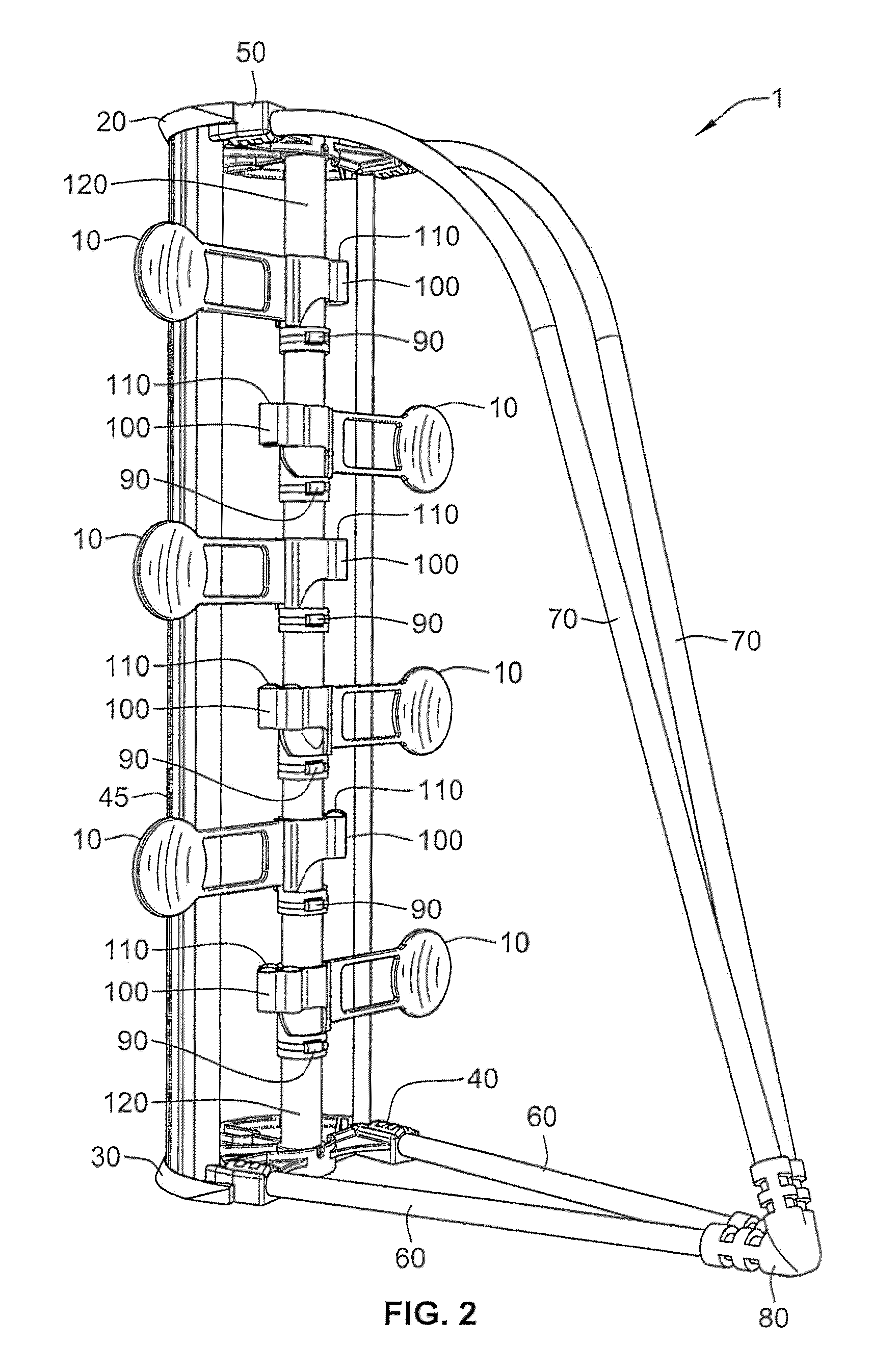
[0033]As shown generally in FIGS. 1-14, and more particularly in FIG. 1, self-resetting paddle target 1 of the present invention is a generally vertical structure comprising at least one (and preferably a plurality) of paddles 10.
[0034]Paddles 10 are configured to extend outwardly, in a generally horizontal orientation, perpendicular to ...
PUM
 Abstract
Description
Claims
Application Information