Connector terminal having electrical wire and connector receiving the same

a technology of connector housing and connector terminal, which is applied in the direction of connection insulation, connection contact member material, coupling device connection, etc., can solve the problem that the electrical wire or the electrical wire crimp portion interferes with the rearward face of the connector housing

Inactive Publication Date: 2010-04-06
YAZAKI CORP
View PDF5 Cites 21 Cited by
  • Summary
  • Abstract
  • Description
  • Claims
  • Application Information

AI Technical Summary

Benefits of technology

[0009]An object of the present invention is to provide a connector terminal, which crimps an electrical wire having an aluminum or aluminum alloy conductor of a large diameter, to be inserted into a terminal receiving chamber of a conventional connector housing designed for an electrical wire having a copper conductor with less change of electrical property and less modification and be adapted for a motor vehicle. The connector terminal including the aluminum conductor thus reduces cost and achieves the lightweight of the motor vehicle, resulting in fuel-efficiency.

Problems solved by technology

When the conventional connector terminal crimping the electrical wire having the aluminum conductor of the large diameter is inserted into the terminal receiving chamber, a part of the electrical wire or the electrical wire crimp portion interferes with the rearward face of the connector housing.

Method used


Image

  • Connector terminal having electrical wire and connector receiving the same
  • Connector terminal having electrical wire and connector receiving the same
  • Connector terminal having electrical wire and connector receiving the same

Examples


first embodiment

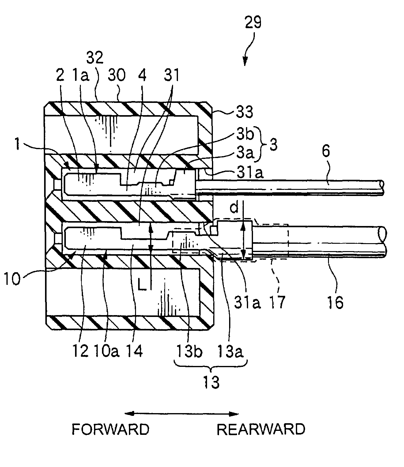
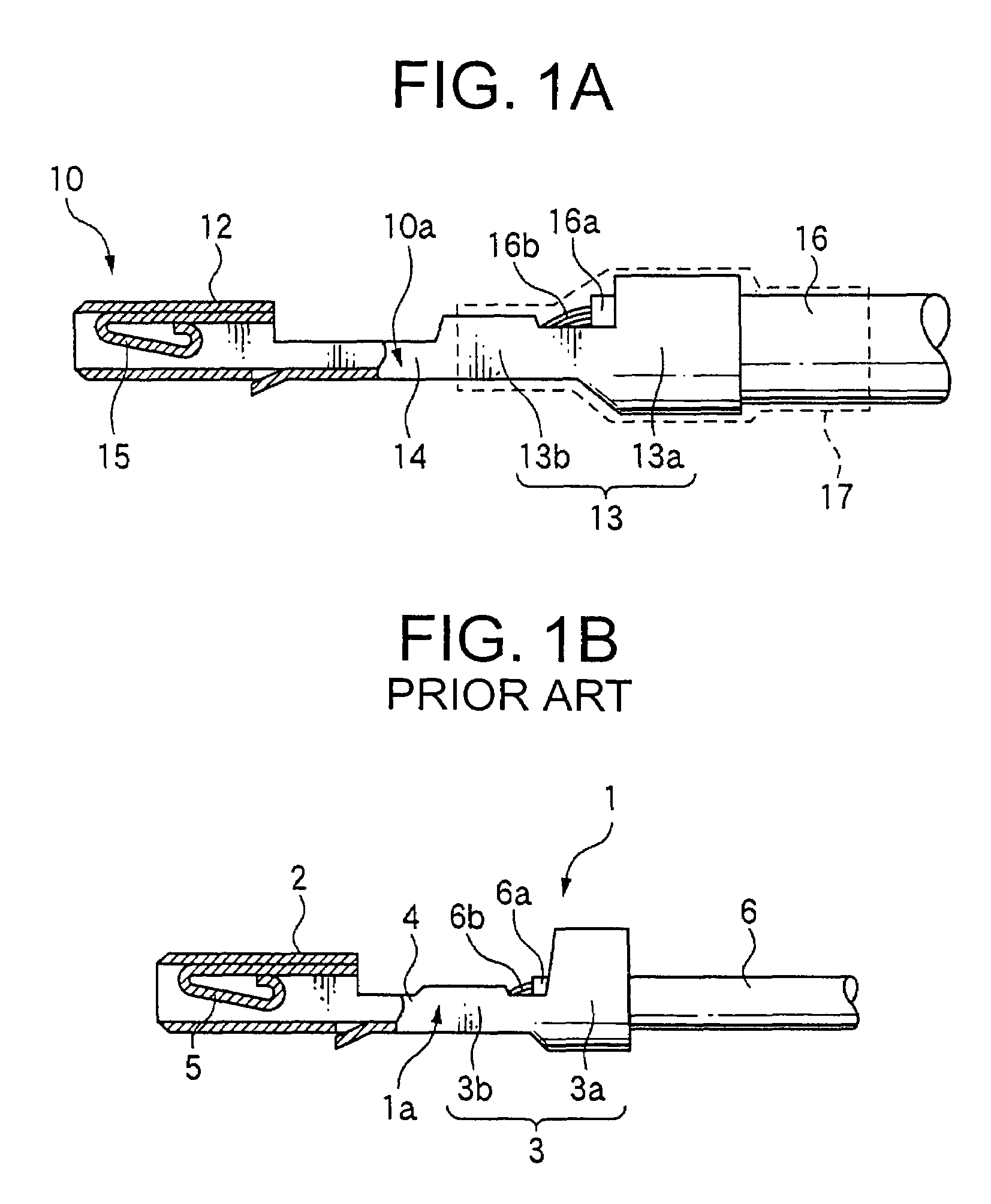
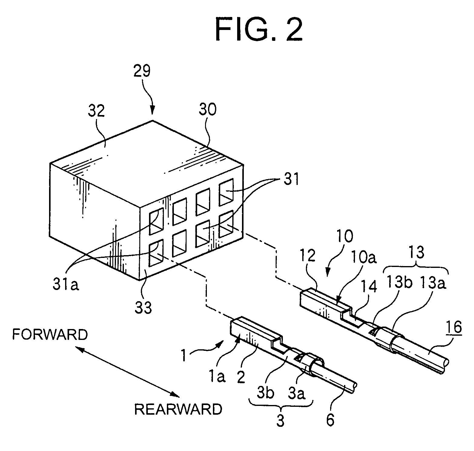
[0029]FIG. 1A is a side view, partly exploded, of a connector terminal 10 having an electrical wire 16 of a first embodiment of the present invention, and FIG. 1B is a side view, partly exploded, of a conventional connector terminal 1 having an electrical wire 6. FIG. 2 is a perspective view of a connector 29 having a conventional connector housing 30 to receive the connector terminal 10 of the present invention and the conventional connector terminal 1. FIG. 3 is a cross-sectional view of the connector 29 having the connector housing 30 receiving the connector terminal 16 of the present invention and the conventional connector terminal 6.

[0030]The connector terminal 1 having the electrical wire 6, hereinafter simply referred to the connector terminal, utilized for a motor vehicle is explained. Electrical wires utilized in the motor vehicle or home electric appliances generally have conductors such as copper materials. The electrical wire having the copper conductor is thus referred...

second embodiment

[0044]FIGS. 4 and 5 show a second embodiment of the present invention. FIG. 4 is a side view, partly exploded, of the second embodiment of a connector terminal 20 and FIG. 5 is a cross-sectional view of the connector 29 receiving the adjacent connector terminals 20 in the connector housing 30. The only difference between the first embodiment and the second embodiment is that the central line C1 of the electrical wire crimp portion 13 is shifted with respect to the central line C2 of the terminal contact portion 12. Like parts as the first embodiment have the same signs and the explanations thereof are omitted.

[0045]Referring to FIG. 4, the connector terminal 20 of the present invention has the terminal contact portion 12, the electrical wire crimp portion 13 and the link portion 14. The terminal contact portion 12 has the same shape as the terminal contact potion 2 of the standard connector terminal 1. The electrical wire crimp portion 13 has the insulation crimp portion 13a and the...


PUM


Abstract

The present invention is to provide a connector terminal, which is crimp connected with an aluminum or aluminum alloy conductor having a large diameter, to be inserted into a terminal receiving chamber of a conventional connector housing designed for a copper conductor with less change of electrical characteristic and less modification. The connector terminal having the conductor of the present invention is widely adapted to a vehicle. The connector terminal crimping the electrical wire has a link portion longer than a link portion of a standard connector terminal so that an electrical wire crimp portion projects outwardly from a rearward face when the connector terminal is received in the connector housing. An insulation crimp portion is positioned spaced apart from the rearward face of the connector housing to prevent physical interference with the connector housing.

Description

BACKGROUND OF THE INVENTION[0001]1. Field of the Invention[0002]The present invention relates to a connector terminal having an electrical wire, and relates to a connector receiving the connector terminal. More specifically, the present invention relates to a connector terminal, which crimps an electrical wire having an aluminum conductor of a diameter larger than a copper conductor, to be inserted into a conventional connector housing designed for an electrical wire having the copper conductor, and relates to a connector receiving the connector terminal having the aluminum conductor.[0003]2. Description of the Related Art[0004]A wiring harness arranged in a motor vehicle generally utilizes the electrical wire having the copper conductor for reasons of low cost and good electrical conductivity. The electrical wire having the aluminum conductor, also including an aluminum alloy conductor, is not usually utilized for reasons of less conductivity and less strength. However, recent envi...

Claims


Application Information

Patent Timeline
Patent Type & Authority Patents(United States)
IPC IPC(8): H01R4/18
CPCH01R4/185H01R4/72H01R13/115H01R4/62
Inventor WATANABE, JINKUGIMIYA, YASUYUKI
Owner YAZAKI CORP
Why Eureka
Try Eureka