Mounting arrangement for a drive unit of a boat, and boat with mounting arrangement for a drive unit

Active Publication Date: 2010-04-06
VOLVO PENTA AB
View PDF7 Cites 25 Cited by
  • Summary
  • Abstract
  • Description
  • Claims
  • Application Information

AI Technical Summary

Benefits of technology

[0004]It is desirable to provide a mounting arrangement for mounting a boat drive to a boat hull that is simple

Problems solved by technology

The rings damp vibrations from the drive to the hull.
A problem with this mounting arrangement is that it does not prevent the drive unit from being moun

Method used


Image

  • Mounting arrangement for a drive unit of a boat, and boat with mounting arrangement for a drive unit
  • Mounting arrangement for a drive unit of a boat, and boat with mounting arrangement for a drive unit
  • Mounting arrangement for a drive unit of a boat, and boat with mounting arrangement for a drive unit

Examples


Embodiment Construction

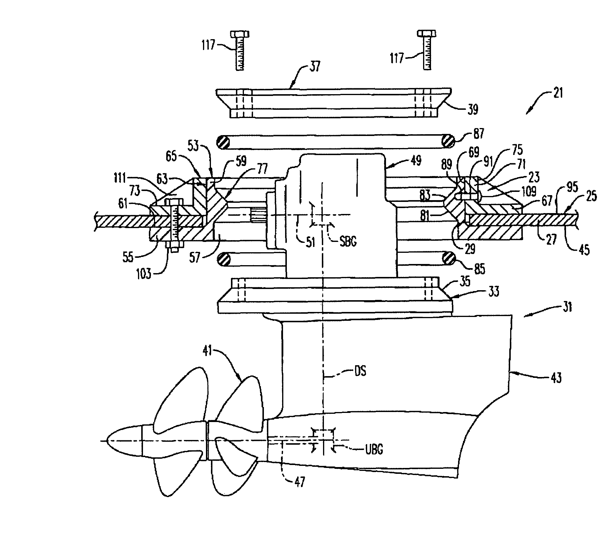
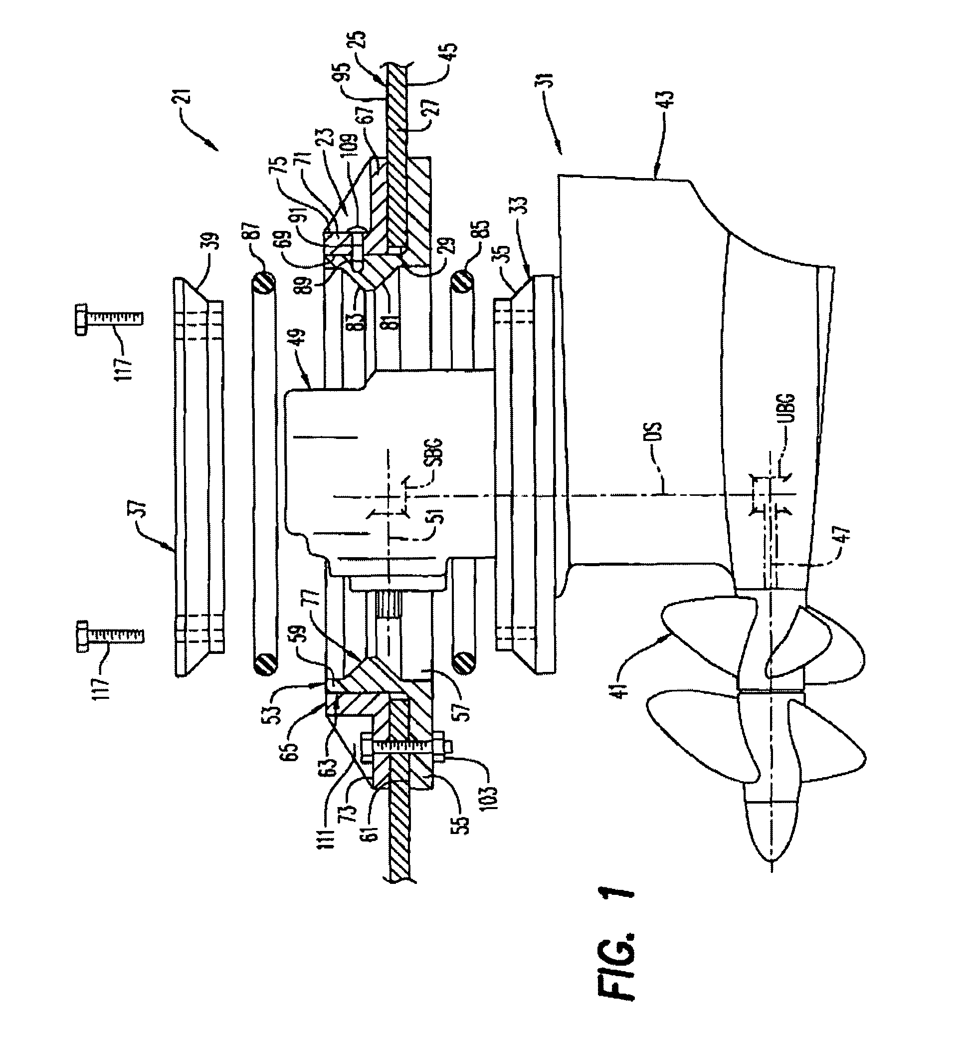
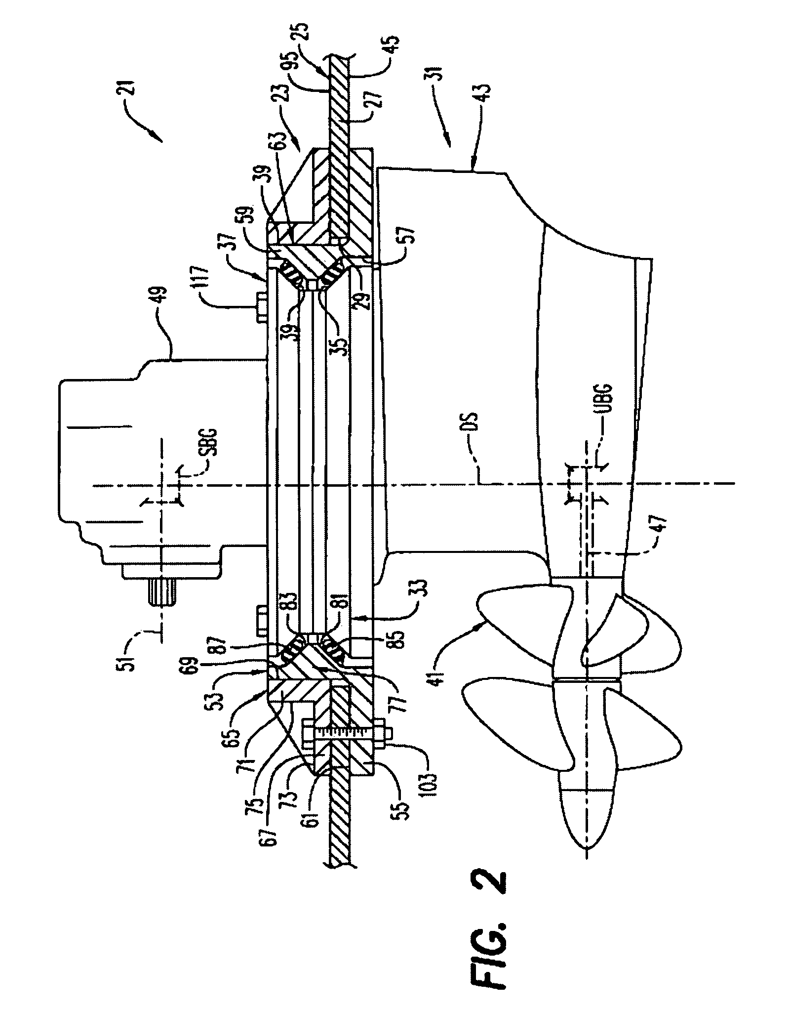
[0015]A portion of a boat 21 having a mounting arrangement 23 for mounting a boat drive unit 31 to a boat hull 25 is shown in FIGS. 1, 2, and 5. As seen in FIGS. 1 and 2, the hull 25 has a wall 27 and an opening 29 extending through the wall. The drive unit 31 comprises a mounting plate 33 having an upwardly facing, substantially frustoconical mounting surface 35. A hold down plate 37 is provided and has a downwardly facing, substantially frustoconical mounting surface 39.

[0016]The drive unit 31 can comprise an outboard drive unit for at least one propeller 41, the drive unit comprising an underwater housing 43 extending down from the outside or bottom 45 of the hull, and an at least substantially vertical drive shaft DS (shown in phantom in FIGS. 1 and 2) being rotatably mounted in the underwater housing, extending through the opening 29 in the bottom of the hull and driving, via a bevel gearing UBG (shown in phantom in FIGS. 1 and 2) enclosed in the underwater housing, at least on...


PUM


Abstract

A mounting arrangement is provided for mounting a boat drive to a boat hull and includes a mounting collar including a first plate having a first opening therein and a first wall extending from a top surface of the first plate around the first opening and defining a first cylinder. The mounting arrangement also includes a clamping collar including a second plate having a second opening therein and a second wall extending from a top surface of the second plate around the second opening and defining a second cylinder, an external shape of at least a top end of the first cylinder substantially matching an internal shape of at least a bottom end of the second cylinder. The first wall of the mounting collar has a first alignment member and the second wall of the clamping collar has a second alignment member, the first alignment member and the second alignment member being positioned so that, when the first plate is mounted against an exterior of the boat hull and the second plate is mounted against an interior of the boat hull with the first cylinder received in the second cylinder, the first alignment member and the second alignment member align when the boat hull is at least a predetermined thickness.

Description

BACKGROUND AND SUMMARY[0001]The present invention relates generally to outboard drive units and, more particularly, for mounting arrangements for outboard drive units.[0002]Certain known outboard drive units have a leg or underwater body extending down from an underside of a hull bottom and have been mounted in different manners. In one case, the leg is rigidly joined to the engine and extends through an opening in the hull bottom, with a rubber bellows or the like forming a seal between the leg and the edge of the surrounding opening. The pushing forces of the propeller are taken up by the engine and the engine mounting. In the second case, the leg or the underwater housing is fixed to a plate which is screwed securely, or fixed in some other manner, to the bottom of the hull. In this case the entire propeller force can be taken up by the hull or a portion can be taken up by the hull and a portion by the drive unit mounted on the inside of the hull, i.e. the engine and transmission...

Claims


Application Information

Patent Timeline
IPC IPC(8): B63H1/15
CPCB63B3/70B63H21/30B63H5/125B63H5/10B63H21/305
Inventor SZILAGYI, EDMUND ALEXANDERANSPACH, DAVID JOHNPELTON, ANDREW ROSS
Owner VOLVO PENTA AB
Why Eureka
Try Eureka