
Sound source localization based on binaural signals

a binaural signal and localization technology, applied in the direction of speech analysis, direction finders using ultrasonic/sonic/infrasonic waves, loudspeaker spatial/constructional arrangement, etc., can solve the problems of significant differences at the signal level between ears, incident sound waves are usually diffracted and damped, etc., to achieve the effect of improving the classification results

Inactive Publication Date: 2010-04-06
HONDA RES INST EUROPE
View PDF8 Cites 6 Cited by
  • Summary
  • Abstract
  • Description
  • Claims
  • Application Information

AI Technical Summary

Benefits of technology

The present invention provides an improved technique of sound source localization based on binaural signals. It involves joint learning and evaluation of ITD and ILD representations that are measured in a complementary, correlation-based way using binaural time-frequency spectrums. The probability distributions over time and frequency are combined to get a robust classification of the location and a confidence measure for the quality of the momentary classification result. The system can also track moving sound sources and improve sound source localization over time. The technical effects of the invention include improved accuracy and reliability of sound source localization and improved ability to track moving sound sources.

Problems solved by technology

In addition, incident sound waves are usually diffracted and damped by the configuration (3D-shape, material) of the recording devices, e.g. a robot head.
This causes a significant difference at the signal levels at the two ears.
However, at high frequencies, where the wavelengths of the sound get short in relation to the head diameter, there may be considerable differences, e.g. due to the head shadow effect.
The contribution of ITD cues to sound source localization is larger for frontally arriving signals and gets poorer with the sound source moving to the side because of a nonlinear dependency of the path difference from the angle of incidence.
Similarly, ILD cues are less accurate at the frontal area because of reduced damping differences.
In conventional methods, three problems concerning azimuthal sound source location remain.
Another problem is how to combine ITD and ILD information that is highly frequency dependent.

Method used


Image

  • Sound source localization based on binaural signals
  • Sound source localization based on binaural signals
  • Sound source localization based on binaural signals

Examples


Embodiment Construction

[0024]One embodiment of the present invention provides techniques for calculating sound source location for binaural signals by using two sound receptors displaced against each other. According to one embodiment of the present invention, two sound receptors are displaced against each other in the azimuthal plane. A further embodiment of the present invention provides for extraction, representation and combination of two types of signals: ITD and ILD / IID.

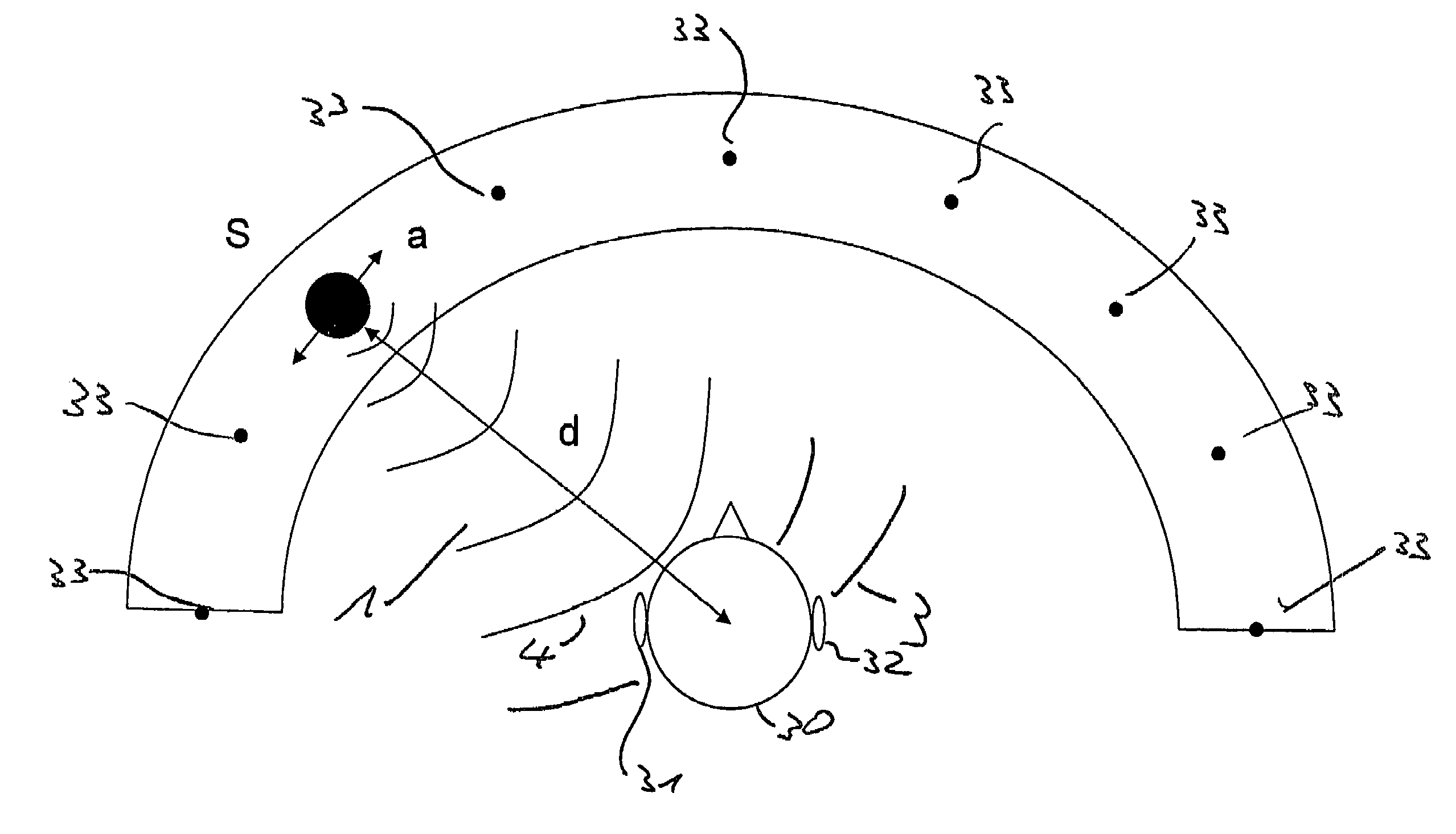
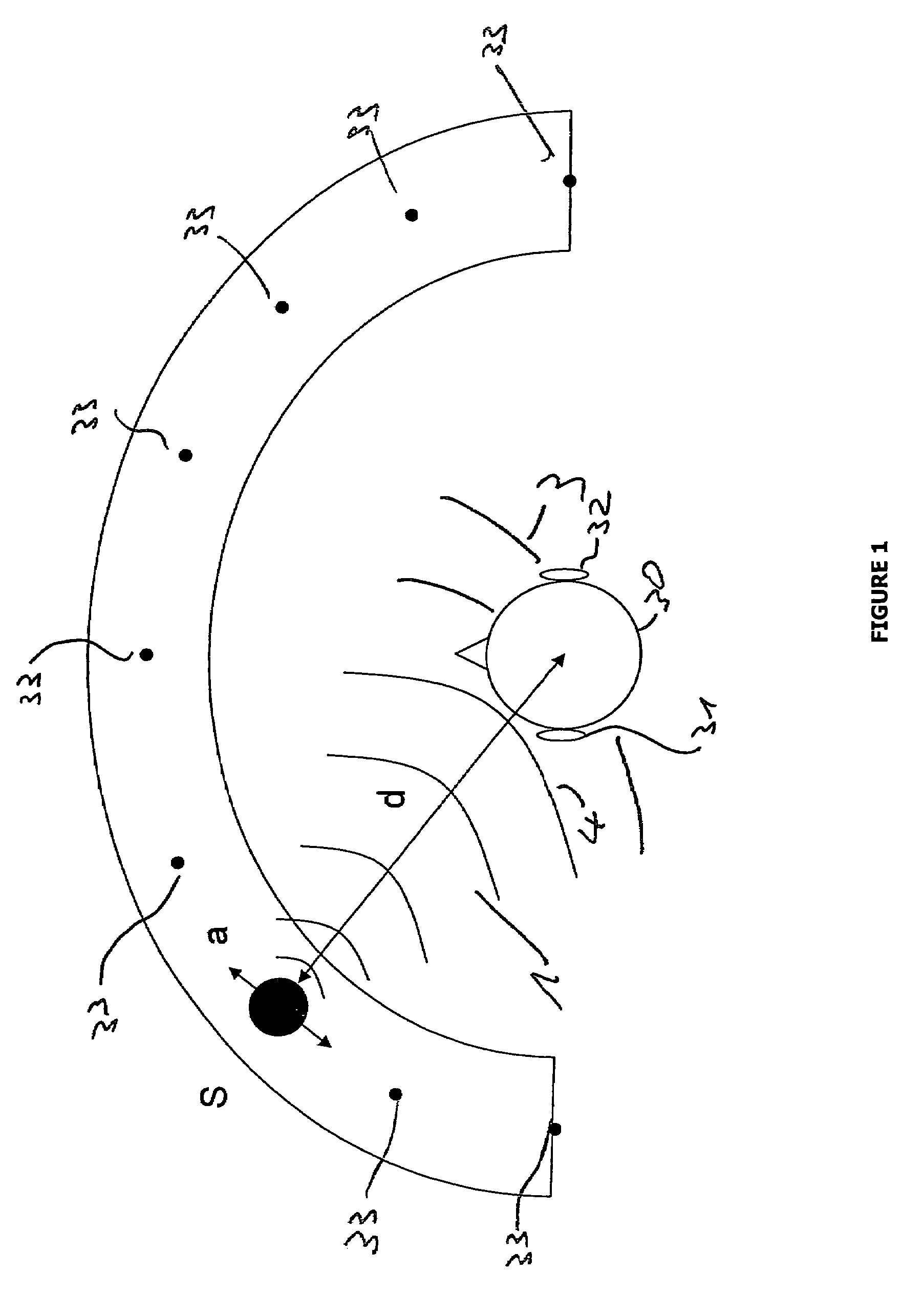
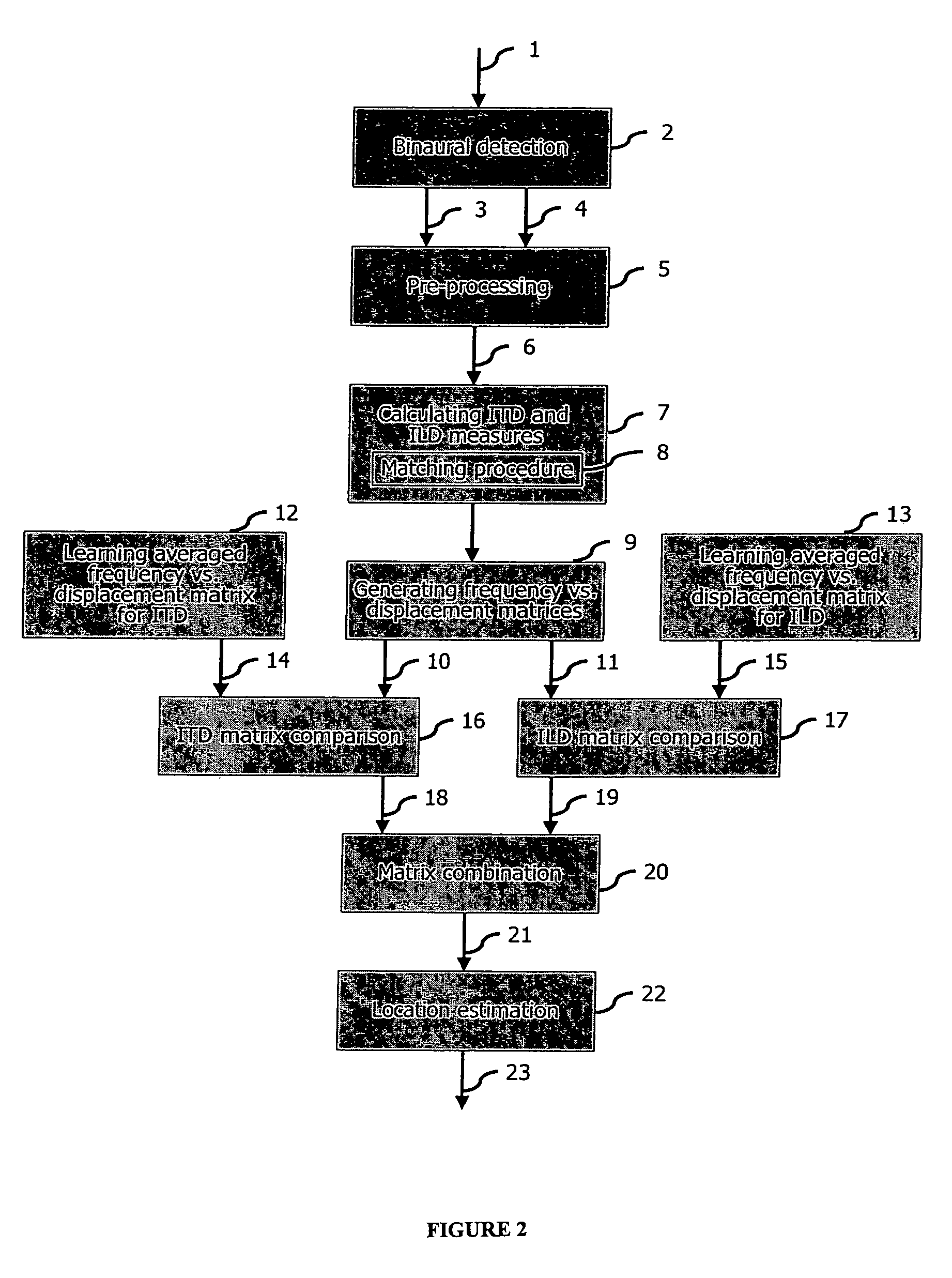
[0025]Sound source localization according to one embodiment of the present invention is now explained with reference to FIG. 1 and FIG. 2.

[0026]A method according to one embodiment of the present invention provides for localization of the origin S of a binaural signal 1 on the basis of two sound signal components 3, 4 detected by a binaural detector 30, i.e. a detector having at least two separated acoustic sensors 31, 32. According to one embodiment of the present invention, the binaural signal 1 is thereby detected 2 by the two sen...


PUM


Abstract

Techniques are disclosed for sound source localization based on joint learning and evaluation of ITD and ILD representations that are measured in a complementary, correlation-based way using binaural time-frequency spectrums. According to one embodiment, from these measurements and learned representatives, which may, for example, be created by combinations of measurements from signals belonging to the same class, i.e., the same azimuthal location, probability distributions over frequency and class are computed. These probability distributions can be combined over cue and frequency using information-theoretic approaches to get a robust classification of the location and additionally a confidence measure for the quality of the classification result.

Description

CROSS-REFERENCE TO RELATED APPLICATIONS[0001]This application is related to and claims priority from European Patent Applications No. 04 012 473.7 filed on May 26, 2004 and 04 030 651.6 filed on Dec. 23, 2004, which are all incorporated by reference herein in their entirety.FIELD OF THE INVENTION[0002]The present invention relates to the field of sound source localization, and especially to sound source localization based on binaural signals.BACKGROUND OF THE INVENTION[0003]One of the primary ways that we separate sounds is to locate them in space. A sound from a fixed sound source arriving at two detectors (e.g. the ears, or two microphones) causes the two measured signals to be displaced in time with each other, due to a difference in transmission time. In a first approximation, this can be thought of as a difference in the straight line path from the sound source to the detectors. The time displacement is called ITD (Interaural Time Differences) and can be used to extract informa...

Claims


Application Information

Patent Timeline
Patent Type & Authority Patents(United States)
IPC IPC(8): H04R5/00H04R5/02G01S3/803G01S3/808G10L21/0216H04S1/00
CPCG01S3/8034G01S3/8083G10L2021/02166
Inventor EGGERT, JULIANWILLERT, VOLKERSTAHL, RAPHAELADAMY, JUERGEN
Owner HONDA RES INST EUROPE
Learn More