
Waveguide structure

a waveguide and waveguide technology, applied in the field of waveguide structure, can solve the problems of effectively suppressing and controlling tdws, and achieve the effect of reducing the tdws of the waveguide and stabilizing the photonic devi

Inactive Publication Date: 2010-04-06
ELECTRONICS & TELECOMM RES INST
View PDF8 Cites 17 Cited by
  • Summary
  • Abstract
  • Description
  • Claims
  • Application Information

AI Technical Summary

Benefits of technology

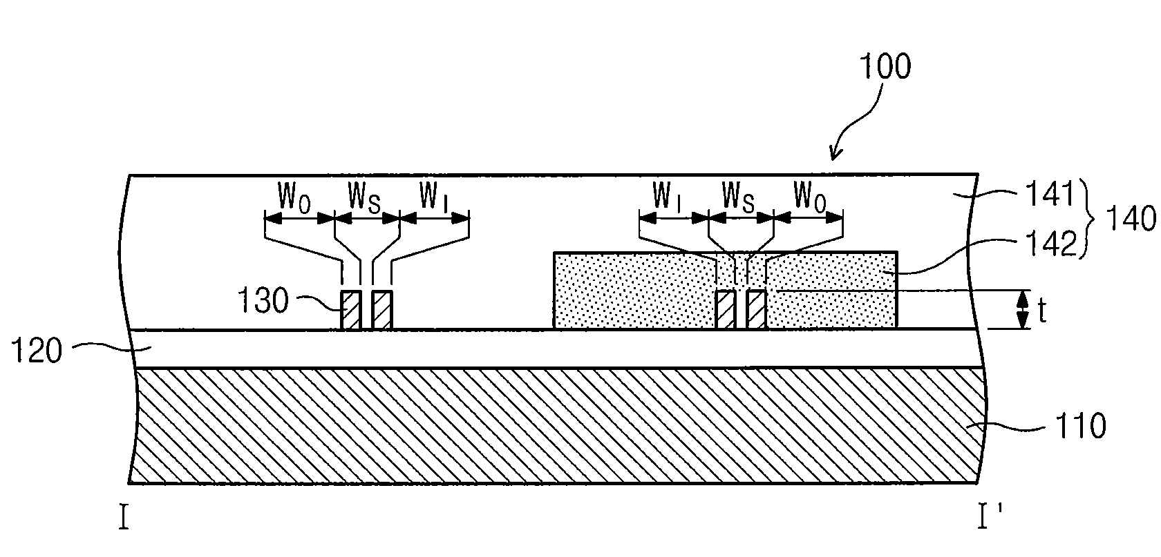
The present invention provides a waveguide structure that can suppress temperature-dependent wavelength shift (TDWS) caused by the material properties of the waveguide and the cladding covering it. This is achieved by using a cladding with a negative temperature coefficient (TOC) and adjusting the thickness of the waveguide, the slot width in the waveguide, the widths of the patterned areas, and the contact area between the cladding and the waveguide. The invention also provides methods for preventing unintentional TDWS and controlling the wavelength shift.

Problems solved by technology

This method is effective in a silica WDM device, whereas it is not available for a WDM device based on silicon having a high TOC because this method cannot effectively suppress the TDWS in the silicon WDM device.
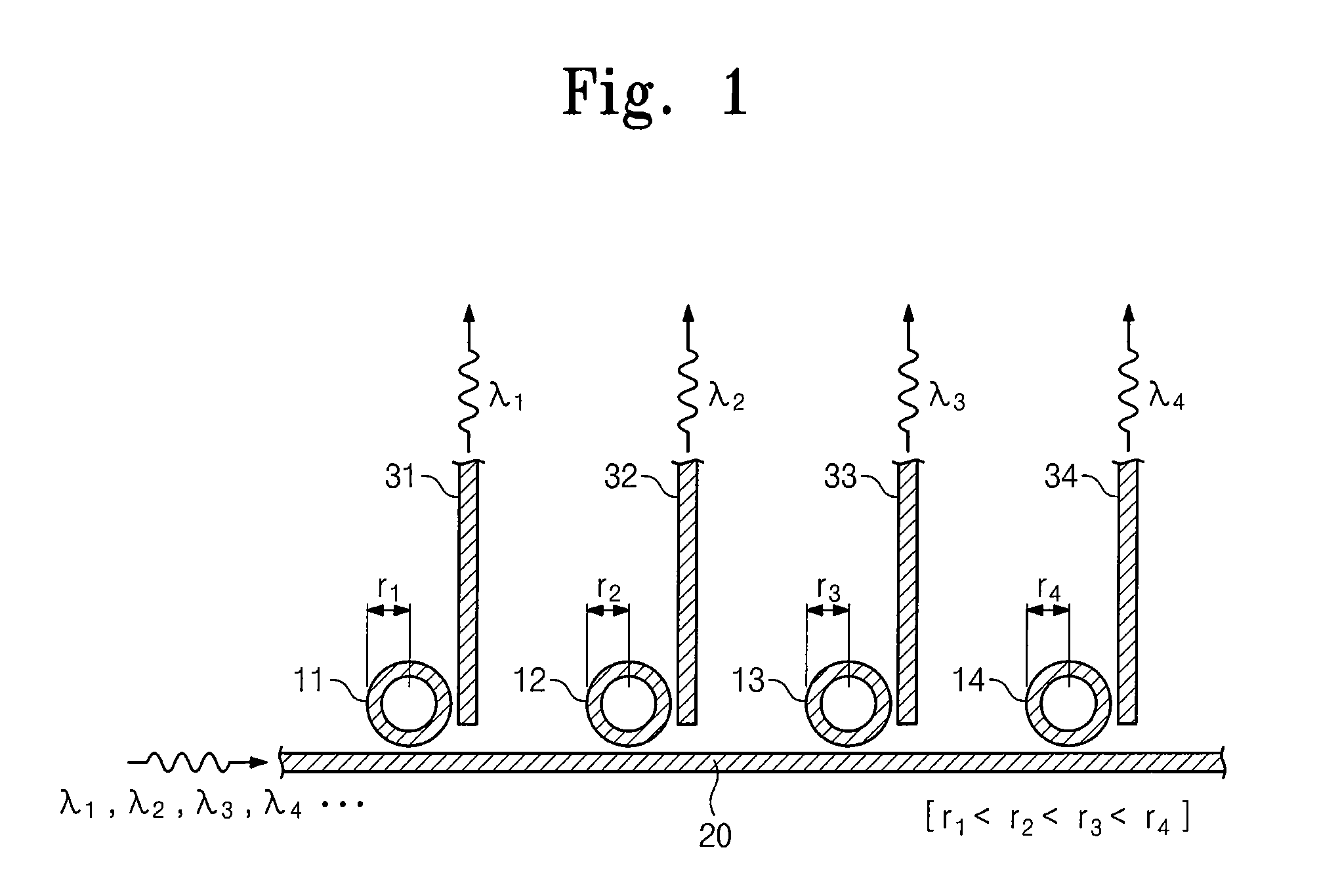
Especially, most of an optical mode is distributed inside a silicon core in a channel waveguide structure of a silicon WDM device, and thus a method of forming a cladding of polymer may not effectively control the TDWS because only a portion of the optical mode is distributed in the cladding.
Furthermore, methods for suppressing TDWS for transverse magnetic (TM) mode was suggested before, but any method for effectively suppressing the TDWS for a transverse electric (TE) mode is not yet suggested.

Method used


Image

  • Waveguide structure
  • Waveguide structure
  • Waveguide structure

Examples


Embodiment Construction

[0043]Preferred embodiments of the present invention will be described below in more detail with reference to the accompanying drawings. The present invention may, however, be embodied in different forms and should not be construed as limited to the embodiments set forth herein. Rather, these embodiments are provided so that this disclosure will be thorough and complete, and will fully convey the scope of the present invention to those skilled in the art.

[0044]In the specification, it will also be understood that when a layer (or film) is referred to as being ‘on’ another layer or substrate, it can be directly on the other layer or substrate, or intervening layers may also be present. In the figures, the dimensions of layers and regions are exaggerated for clarity of illustration. Also, though terms like a first, a second, and a third are used to describe various regions and layers in various embodiments of the present invention, the regions and the layers are not limited to these t...


PUM


Abstract

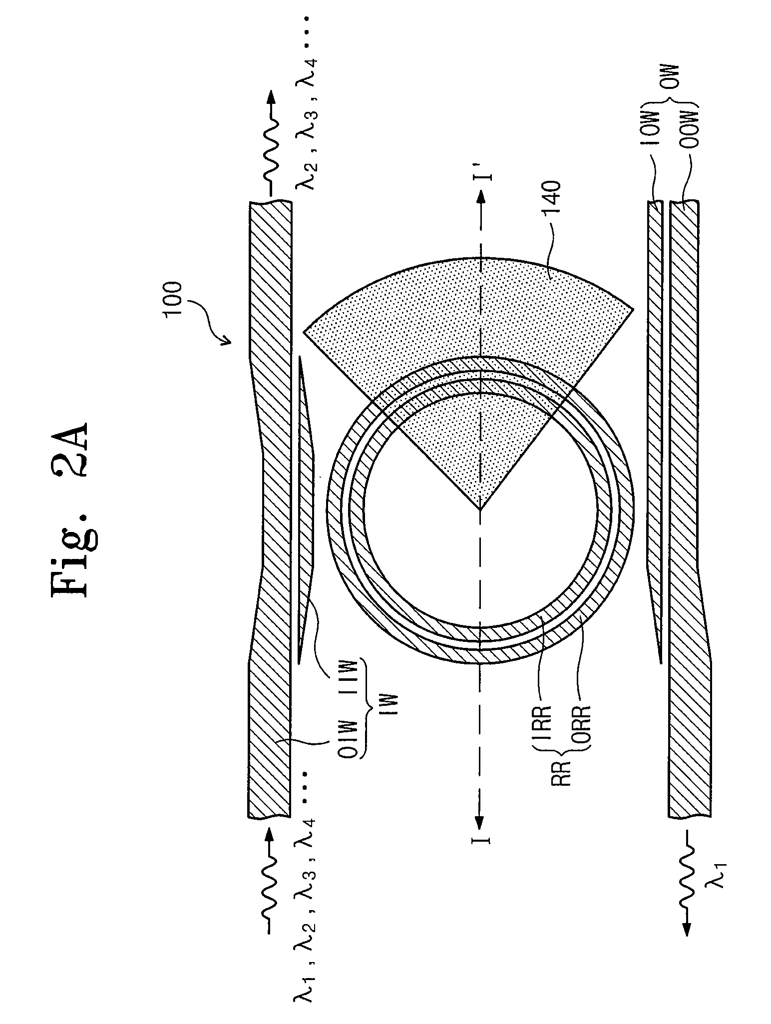
A waveguide structure is provided. The waveguide structure includes: a slot channel waveguide including first and second patterns, which are spaced apart from each other to define a slot; a first upper layer covering at least a portion of the slot channel waveguide; and a second upper layer covering the remaining portion of the slot channel waveguide. A thermo-optic coefficient (TOC) of the channel waveguide times a TOC of the second upper layer is a negative number.

Description

CROSS-REFERENCE TO RELATED APPLICATIONS[0001]This U.S. non-provisional patent application claims priority under 35 U.S.C. § 119 of Korean Patent Application No. 10-2007-127813, filed on Dec. 10, 2007, the entire contents of which are hereby incorporated by reference.BACKGROUND OF THE INVENTION[0002]The present invention disclosed herein relates to a photonic device, and more particularly, to a waveguide structure capable of reducing temperature-dependent wavelength shift (TDWS).[0003]The present invention has been derived from research undertaken as a part of the information technology (IT) development business by the Ministry of Information and Communication and the Institute for Information Technology Advancement of the Republic of Korea [Project management No.: 2006-S-004-02, Project title: silicon based ultra high speed optical interconnection IC].[0004]Optical interconnection technology can be used to realize a high speed bus of a semiconductor device such as a central processi...

Claims


Application Information

Patent Timeline
Patent Type & Authority Patents(United States)
IPC IPC(8): G02B6/10
CPCG02B6/12007G02B6/12
Inventor LEE, JONG-MOOKIM, DUK-JUNKWON, O-KYUNKIM, GYUNG-OCK
Owner ELECTRONICS & TELECOMM RES INST
Learn More