Monitoring unit state chart and a debounce logic

a unit state chart and logic technology, applied in the direction of instruments, machines/engines, analogue processes for specific applications, etc., can solve the problem that the engine may reduce at least one of engine torque or engine speed

Inactive Publication Date: 2010-04-06
DETROIT DIESEL CORP
View PDF18 Cites 8 Cited by
  • Summary
  • Abstract
  • Description
  • Claims
  • Application Information

AI Technical Summary

Benefits of technology

[0012]logging any faults after debounce filtering in a fault control module and activating any alerts indicating said faults.The motor control module faults monitoring units are updated once per second, and the Common Powertrain Controller includes monitoring units that may be evaluated up to 10 times per second. When a fault is logged, the engine may reduce at least one of engine torque or engine speed.

Problems solved by technology

When a fault is logged, the engine may reduce at least one of engine torque or engine speed.

Method used


Image

  • Monitoring unit state chart and a debounce logic
  • Monitoring unit state chart and a debounce logic
  • Monitoring unit state chart and a debounce logic

Examples


Embodiment Construction

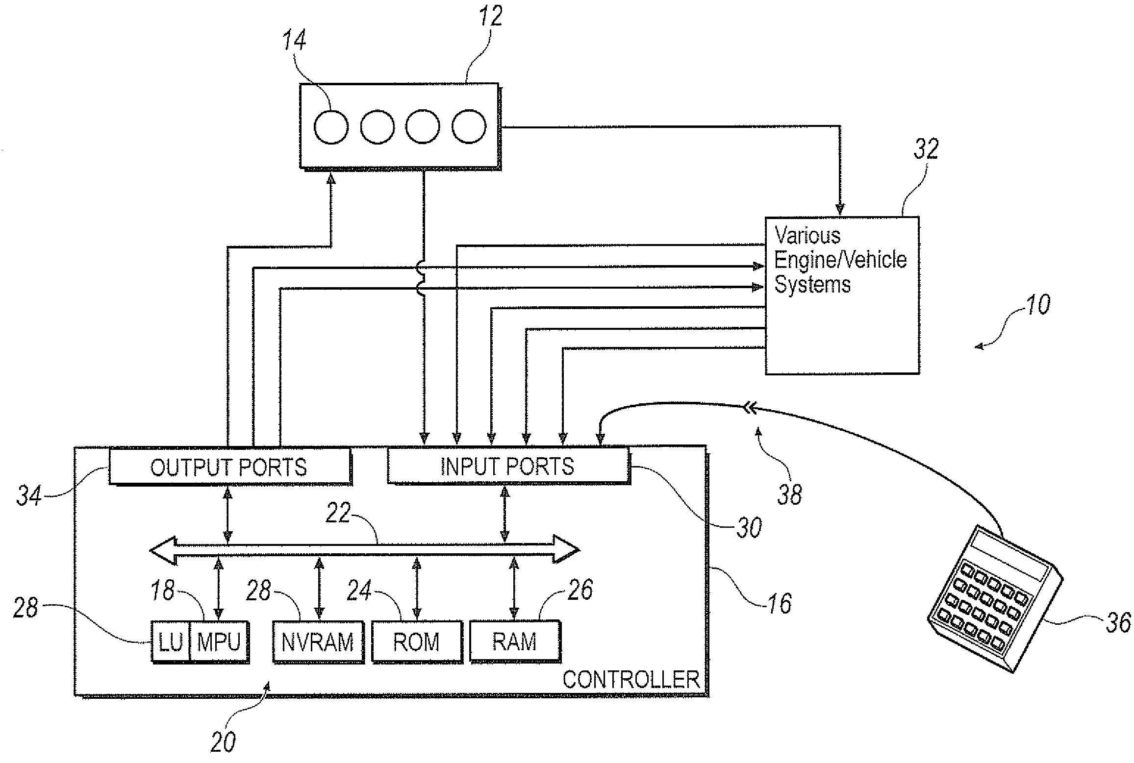
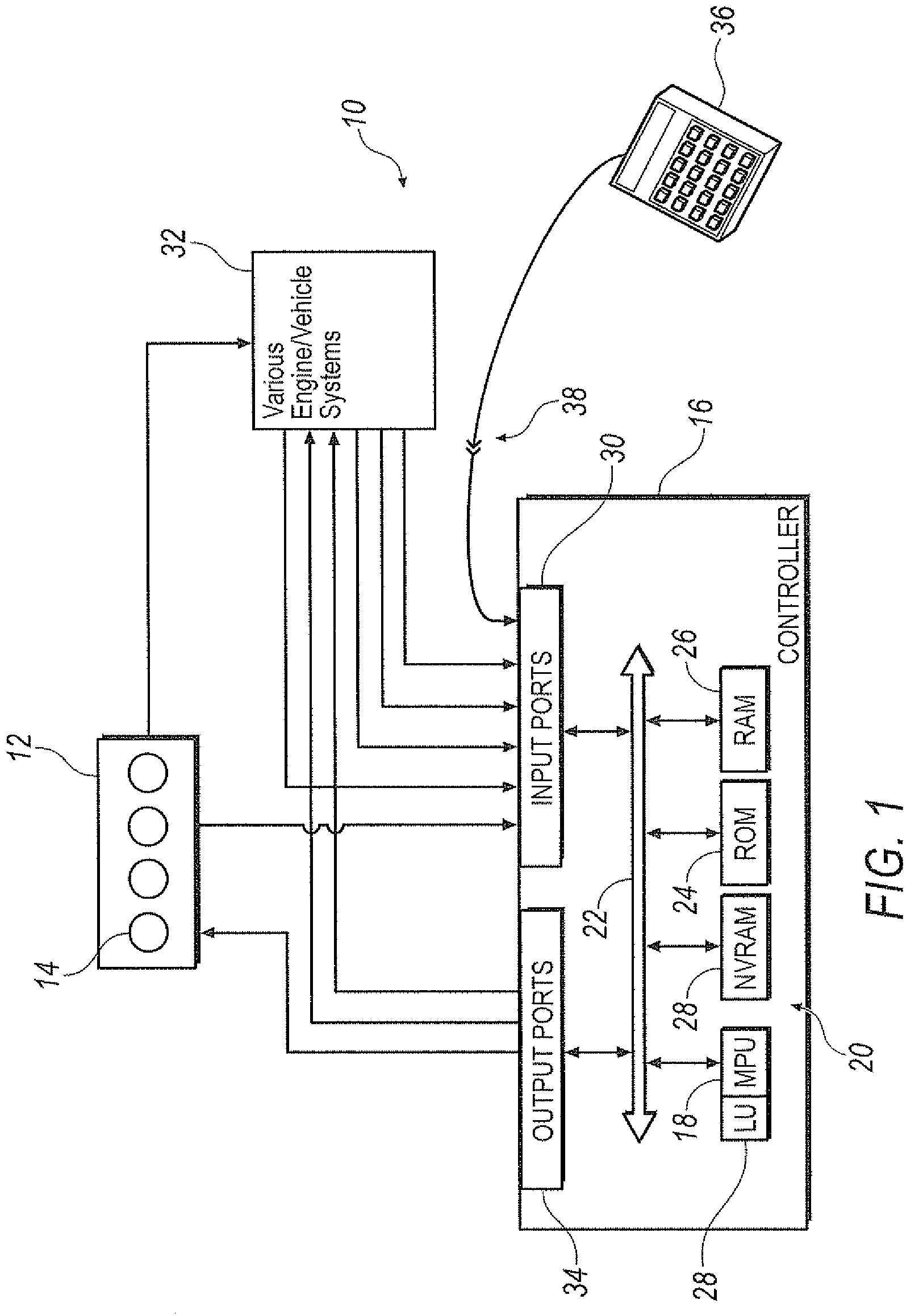
[0017]Turning now to the drawings where like numerals depict like structures and particularly to FIG. 1, there is schematically represented a diagrammatic view illustrating a compression-ignition internal combustion engine system 10 incorporating various features according to the present invention is shown. The engine 12 may be implemented in a wide variety of applications including on-highway trucks, construction equipment, marine vessels, stationary generators, pumping stations, and the like. The engine 12 generally includes a plurality of cylinders disposed below a corresponding cover, indicated generally by reference numeral 14.

[0018]In a preferred embodiment, the engine 12 is a multi-cylinder compression ignition internal combustion engine, such as a 3, 4, 6, 8, 12, 16, or 24 cylinder diesel engine. However, the engine 12 may be implemented having any appropriate number of cylinders 14, the cylinders having any appropriate displacement and compression ratio to meet the design c...


PUM


Abstract

A method of logging faults in an electronic controlled internal combustion engine that passes any fault readings through a debounce logic to determine whether the fault indication is real.

Description

CROSS-REFERENCE TO RELATED APPLICATIONS[0001]The present application claims priority to U.S. Provisional Application Ser. No. 60 / 877,928 filed on Dec. 29, 2006, the contents of which are incorporated herein in their entirety.BACKGROUND OF THE INVENTION[0002]1. Field of the Invention[0003]The present invention relates to a method of logging faults in memory in an electronic controlled internal combustion engine having an electronic control unit with memory.[0004]The present invention further relates to a method of filtering data signals through a debounce logic to filter erroneous fault signals.[0005]2. Description of Related Art[0006]Young U.S. Pat. No. 6,157,671 discloses a circuit for digitally monitoring a duty cycle of a pulse width modulated signal. The circuit includes s counter portion, a digital filter, and a data storage device. The counter portion is connectable to receive the pulse width modulated signal and is operable to monitor the pulse width modulated signal for a pr...

Claims


Application Information

Patent Timeline
Patent Type & Authority Patents(United States)
IPC IPC(8): G06G7/64
CPCG07C5/085B60W50/0205
Inventor GROER, FRANK S.GOLUB, TOMISLAV I.
Owner DETROIT DIESEL CORP
Why Eureka
Try Eureka