RFID tag and manufacturing process thereof
a technology of RFID tags and manufacturing processes, applied in the field of RFID tags, can solve the problems of low reliability, large number of parts, and no improvement in regard to achieving improvement, and achieve the effects of reducing manufacturing steps, high reliability, and reducing thickness
- Summary
- Abstract
- Description
- Claims
- Application Information
AI Technical Summary
Benefits of technology
Problems solved by technology
Method used
Image
Examples
first embodiment
[0076]Hereinafter, explanation will be made on a first embodiment of the present invention.
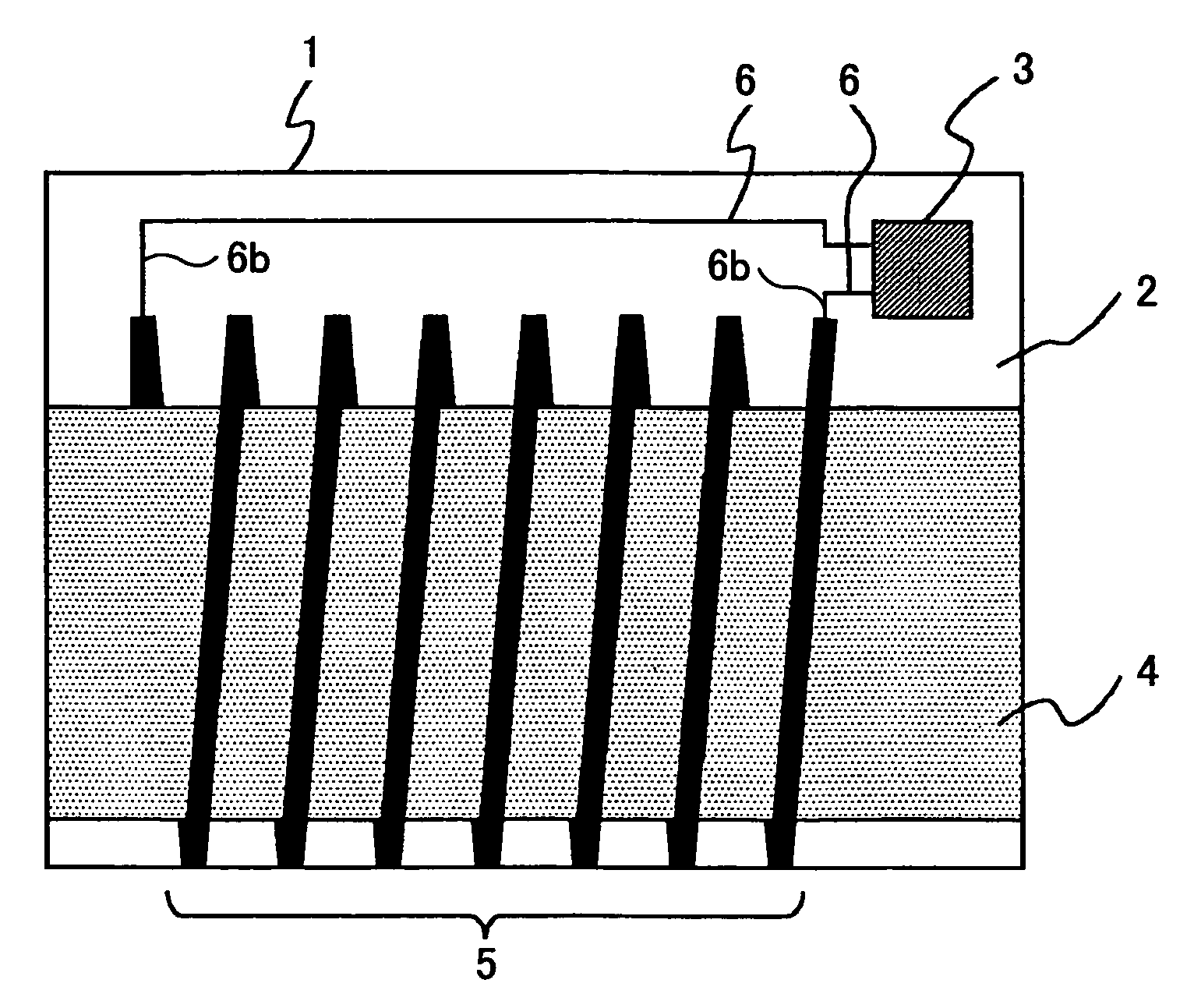
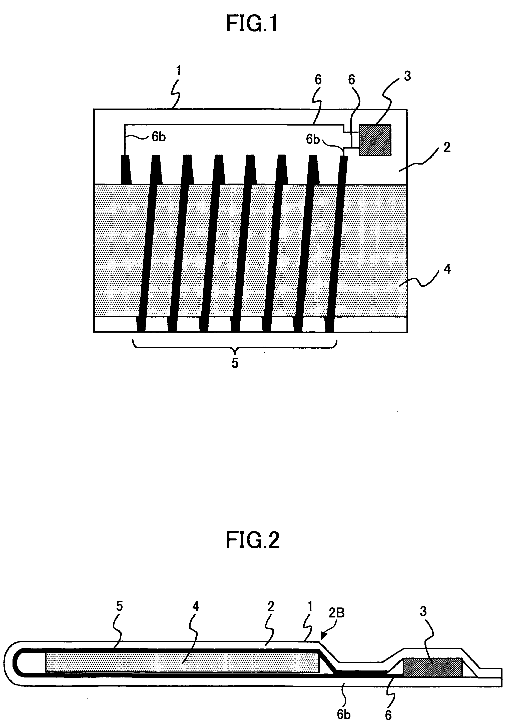
[0077]FIG. 1 shows the construction of an RFID 1 of to the present embodiment, while FIG. 2 shows the cross-sectional structure of the RFID tag 1.
[0078]Referring to FIGS. 1 and 2, the RFID tag 1 includes an insulation sheet 2, a semiconductor chip 3, a magnetic core member 4, a coil pattern 5 and an interconnection pattern 6, wherein the coil pattern 5 and the semiconductor chip 3 are formed on the same side of the insulation sheet 2, and the insulation sheet 2, carrying thereon the coil pattern 5, covers the semiconductor chip 3 and wraps around the magnetic core member 4.
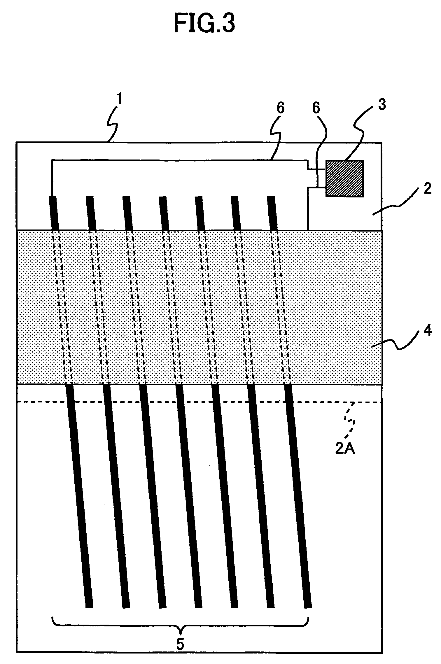
[0079]FIG. 3 shows the RFID tag 1 in the state before completion of the assembling.
[0080]Referring to FIG. 3, it can be seen that there are formed parallel, bar-shaped conductor patterns forming together a coil pattern 5 on one side of the insulation sheet 2, and another conductor pattern forming the interconnection pattern ...
second embodiment
[0099]Next, a second embodiment of the present invention will be explained, wherein those parts corresponding to the parts described previously are designated by the same reference numerals and the description thereof will be omitted.
[0100]FIG. 4 shows the construction of an RFID tag according to the present embodiment, while FIG. 5 shows the cross-section of the RFID tag of the present embodiment.
[0101]Referring to FIGS. 4 and 5, the RFID tag of the present embodiment has a generally identical construction to the RFID tag of the first embodiment, except that the insulation sheet 2 is now formed of a lower insulation sheet 2A and an upper insulation sheet 2B.
[0102]Thus, with the present embodiment, the coil pattern 5 is also divided into a lower coil pattern part 5A provided on the lower insulation sheet 5A and an upper coil pattern part 5B provided on the upper insulation sheet 5B.
[0103]Assembling of the RFID tag 1 of the present embodiment is conducted similarly to the case of the...
third embodiment
[0105]Next, a third embodiment of the present invention will be described.
[0106]FIG. 7 shows the construction of the RFID tag according to the third embodiment of the present invention, wherein those parts corresponding to the parts described previously are designated by the same reference numerals and the description thereof will be omitted.
[0107]Referring to FIG. 7, the RFID tag of the present embodiment has a construction similar to that of the RFID tag of the second embodiment, except that there is provided a thermal paper 19 on a flat surface of the RFID tag via an adhesion layer 18.
[0108]Here, it should be noted that the thermal paper 19 is a rewritable thermal paper while the adhesive layer 18 may be formed by applying a sticking layer or a both-side adhesive film.
[0109]With the use of such a rewritable thermal paper 19, in which the part applied with heat changes dark, it is possible to represent or display characters or images by using a thermal print head. Further, such ch...
PUM
 Abstract
Description
Claims
Application Information
 - R&D
- Intellectual Property
- Life Sciences
- Materials
- Tech Scout
- Unparalleled Data Quality
- Higher Quality Content
- 60% Fewer Hallucinations
Browse by: Latest US Patents, China's latest patents, Technical Efficacy Thesaurus, Application Domain, Technology Topic, Popular Technical Reports.
© 2025 PatSnap. All rights reserved.Legal|Privacy policy|Modern Slavery Act Transparency Statement|Sitemap|About US| Contact US: help@patsnap.com


