Cam-lift for a manhole cover

a manhole cover and cam-lift technology, which is applied in the direction of building roofs, foundation engineering, artificial islands, etc., can solve the problems of reducing the design and production efficiency of manhole covers, affecting the safety of workers, so as to achieve the effect of minimal force and effor

Active Publication Date: 2010-04-13
NEENAH FOUNDRY
View PDF14 Cites 32 Cited by
  • Summary
  • Abstract
  • Description
  • Claims
  • Application Information

AI Technical Summary

Benefits of technology

[0009]The present invention addresses the hazards and problems associated with manipulating current manhole cover assemblies. In particular, the present invention includes an assembly for conveniently raising a cover from an opening, rotating a cover away from and back over an opening, and lowering a cover back onto an opening. The cover can be raised, rotated, and lowered with minimal force and effort by a single worker using the present invention.

Problems solved by technology

As a result, the type of materials used as well as the type and amount of secondary manufacturing operations employed in the design and production of manhole covers is limited.
Covers range in size depending upon the application and can be very heavy.
Furthermore, due to the durability, strength, cost, and application requirements discussed above, manhole covers are typically cast iron and weigh between thirty to over one-hundred and thirty kilograms.
The size and weight of many manhole covers combine to create a heavy, awkward cover and give rise to several potential hazards and problems.
Workers having to remove and lift larger covers are susceptible to accidental injuries should the cover slip and land upon a hand, leg, foot, or other body part.
Repeated lifting of heavy covers may lead to chronic physical ailments requiring painful and expensive rehabilitation.
The demanding physical requirements imposed by the size and weight of some covers limits the pool of workers capable of individually manipulating a cover.

Method used


Image

  • Cam-lift for a manhole cover
  • Cam-lift for a manhole cover
  • Cam-lift for a manhole cover

Examples


Embodiment Construction

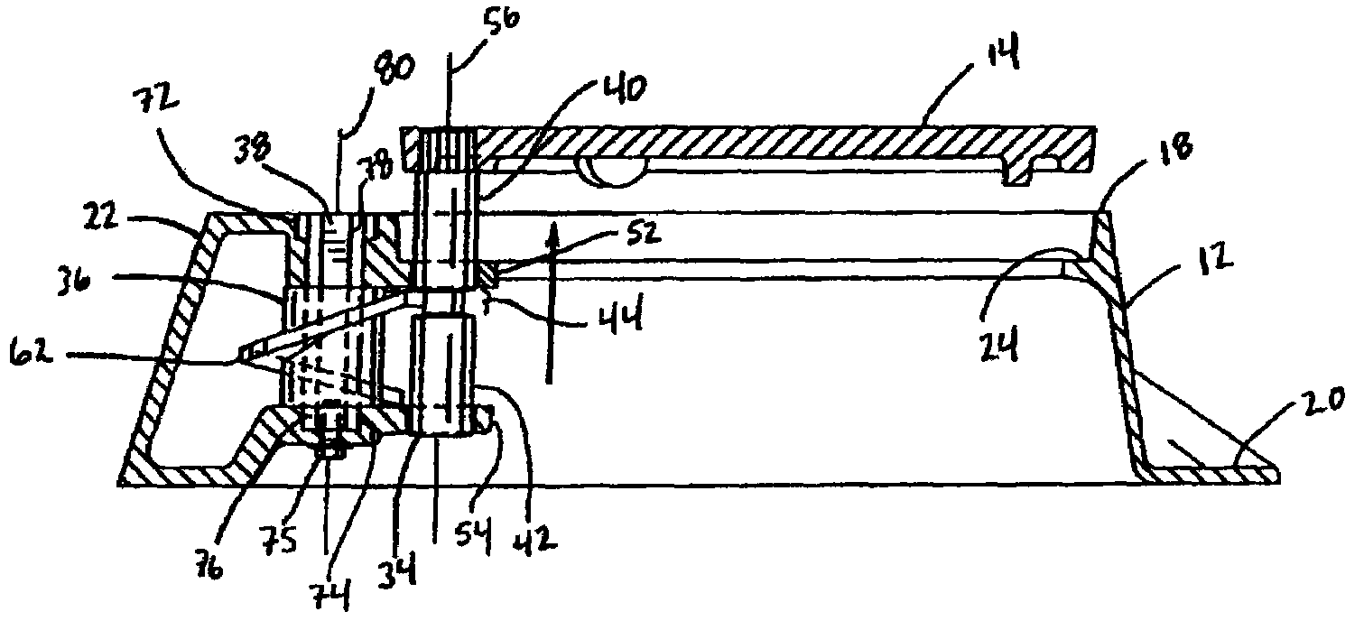
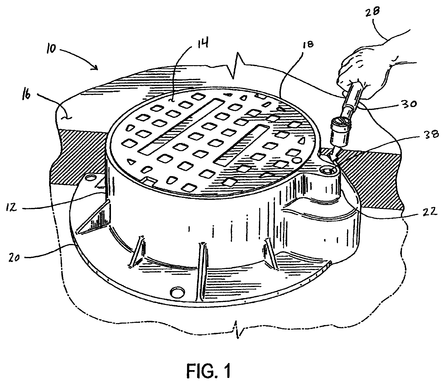
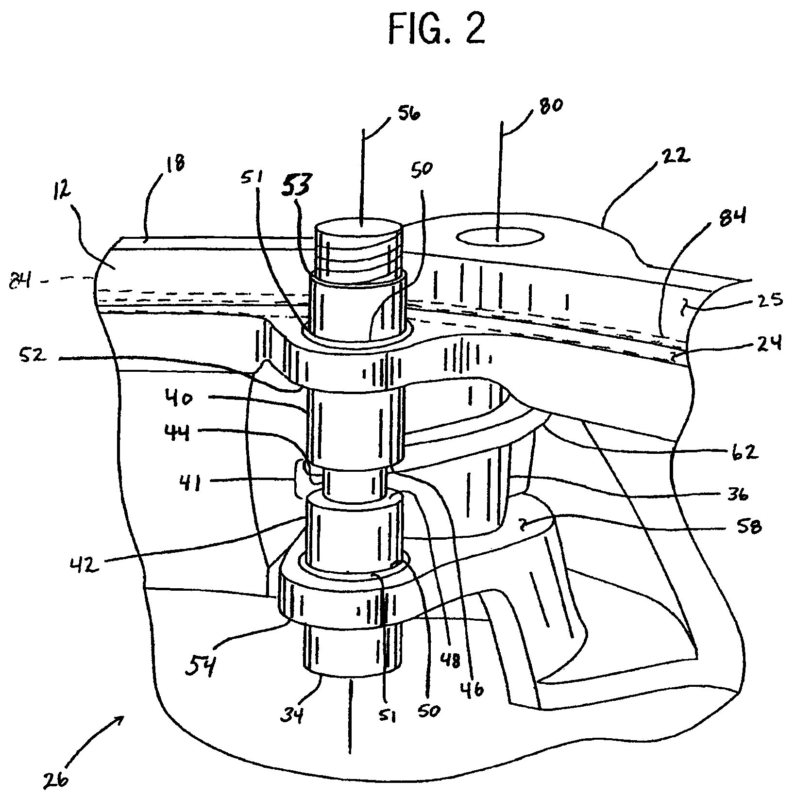
[0023]A manhole cover assembly is generally designated by reference number 10, as shown in FIG. 1. The manhole cover assembly includes a frame 12 and a cover 14. A half round housing 22 of the frame 12 houses a cam-lift assembly 26, in accordance with the present invention, for raising, rotating, and lowering the cover 14 (described in detail below and shown in FIG. 2). The frame 12 is typically manufactured from gray cast iron, but may be made of any suitable material, such as steel, aluminum, or plastic, provided the material is capable of meeting the application requirements. As shown in FIGS. 1 and 3, the frame 12 is usually recessed below an application surface 16 (e.g., roadway, sidewalk, and the like) so that an upper rim 18 of the frame 12 is flush with the application surface 16. The frame 12 of the preferred embodiment is circular (as viewed from above as shown in FIG. 1); however, the frame 12 may be any suitable shape, such as square, rectangular, octagonal, and the like...


PUM


Abstract

A manhole cover assembly including a frame defining an opening and a cover sized to engage the opening. A lift pin is retained by the frame, defining a first axis, and includes a bearing portion, and a top end connected to the cover. The lift pin is free to slide axially along the first axis. A spiral cam is retained to the frame by a torque shaft including an upper and lower end, defining a second axis offset from the first axis. The spiral cam includes a cam surface in selective engagement with the bearing portion of the lift pin so that rotation of the torque shaft about the second axis causes rotation of the spiral cam about the second axis and displacement of the lift pin along the first axis.

Description

CROSS-REFERENCE TO RELATED APPLICATION[0001]This claims the benefit of U.S. Provisional Patent Application No. 61 / 013,181 filed Dec. 12, 2007.STATEMENT CONCERNING FEDERALLY SPONSORED RESEARCH OR DEVELOPMENT[0002]Not applicable.FIELD OF THE INVENTION[0003]The present invention relates to a manhole cover assembly and more particularly a cam-lift for use in a manhole cover.BACKGROUND OF THE INVENTION[0004]Underground passages are prevalent in developed areas and provide passageways for everything from fiber optic data lines, to sewage, to electrical power transmission lines. Workers require access to the underground passageways to perform routine maintenance and to correct defects that may occur to the utility passing within. Thus, the manhole cover was created to close off the passageways and still provide a means of ingress and egress to the passageways.[0005]A manhole cover must be durable, strong, and relatively inexpensive. Durability is required as many cover applications are exp...

Claims


Application Information

Patent Timeline
Patent Type & Authority Patents(United States)
IPC IPC(8): E06B11/00
CPCE02D29/1427E02D29/14
Inventor AKKALA, STEVEN M.REMME, RANDY P.
Owner NEENAH FOUNDRY
Why Eureka
Try Eureka