Endoscope connector device, endoscope cable lead-out unit and endoscope device

a technology of connector devices and endoscopes, which is applied in the direction of coupling device connections, instruments, applications, etc., can solve the problems of troublesome connection, difficult cleaning between, and difficult /i>connection

Inactive Publication Date: 2010-04-13
FUJI PHOTO OPTICAL CO LTD
View PDF28 Cites 59 Cited by
  • Summary
  • Abstract
  • Description
  • Claims
  • Application Information

AI Technical Summary

Benefits of technology

[0018]The invention was made in view of the above-described problems, and a first object thereof is to provide an endoscope connector device that is easy to be used and has advantages in that excellent access to the operation part can be secured by widening the front side space of the front panels of the light source unit or the processor unit, and makes cable connections to the light source unit and the processor unit easy, and cleaning performance is high.
[0019]The invention was made in view of the above-described problems, and a second object thereof is to provide an endoscope cable lead-out unit which can eliminate the possibility of breakage of the synthetic resin-including outer sheath, makes leading-out and assembling of the cable easy, and realizes a simple construction in the case where the cable is taken out from the main body.
[0029]According to the construction of the fourth aspect, a metallic frame of the lead-out part independent from the metallic supporting member of the main body side is disposed inside the outer sheath, and the synthetic resin-including outer sheath is nipped by this frame and the presser ring, whereby the metallic frame that retains the cable or components thereof is easily attached inside the lead-out part outer sheath.
[0030]According to the construction of the fifth aspect, the synthetic resin-including outer sheath is nipped by the first frame and the presser ring on the side of the second frame, whereby the second frame that retains the cable or components thereof is easily attached inside the lead-out part outer sheath.

Problems solved by technology

However, the related-art endoscope connector devices have the following problems.
Furthermore, in the endoscope apparatus of FIG. 8, obstruction of access to the operation part of the front panel as described above is rare, however, the upper and lower cables 57a and 57c attached to the connector part 57b are adjacent to each other, so that cleaning between these cables 57a and 57c becomes difficult.
However, in many endoscopes, it is required that the control portion (51A of FIG. 7) is held by the left hand and the light guide connector (light source part connector) is inserted into the light source unit by the right hand and then the cable and connector positioned on the left hand side are held and connected to the signal processing unit (processor unit), and this connection is troublesome.
However, in this case, the connectors of the two branched cables swing as pendulums, and the connectors themselves may be broken due to collision of these.
In addition, tightening and fixing of the plurality of screws (4) for connecting the connector receiver 3b are troublesome.
In order to avoid such breakage of the plastic-made lead-out part outer sheath 1b, it is considered that the lead-out part is reinforced by arranging a metallic supporter inside the lead-out part, however, in this case, it is necessary that the metallic supporter of the lead-out part is fixed to the metallic supporter or the like inside the light guide connector main body by some method, and this fixing method becomes complicated.

Method used


Image

  • Endoscope connector device, endoscope cable lead-out unit and endoscope device
  • Endoscope connector device, endoscope cable lead-out unit and endoscope device
  • Endoscope connector device, endoscope cable lead-out unit and endoscope device

Examples


first embodiment

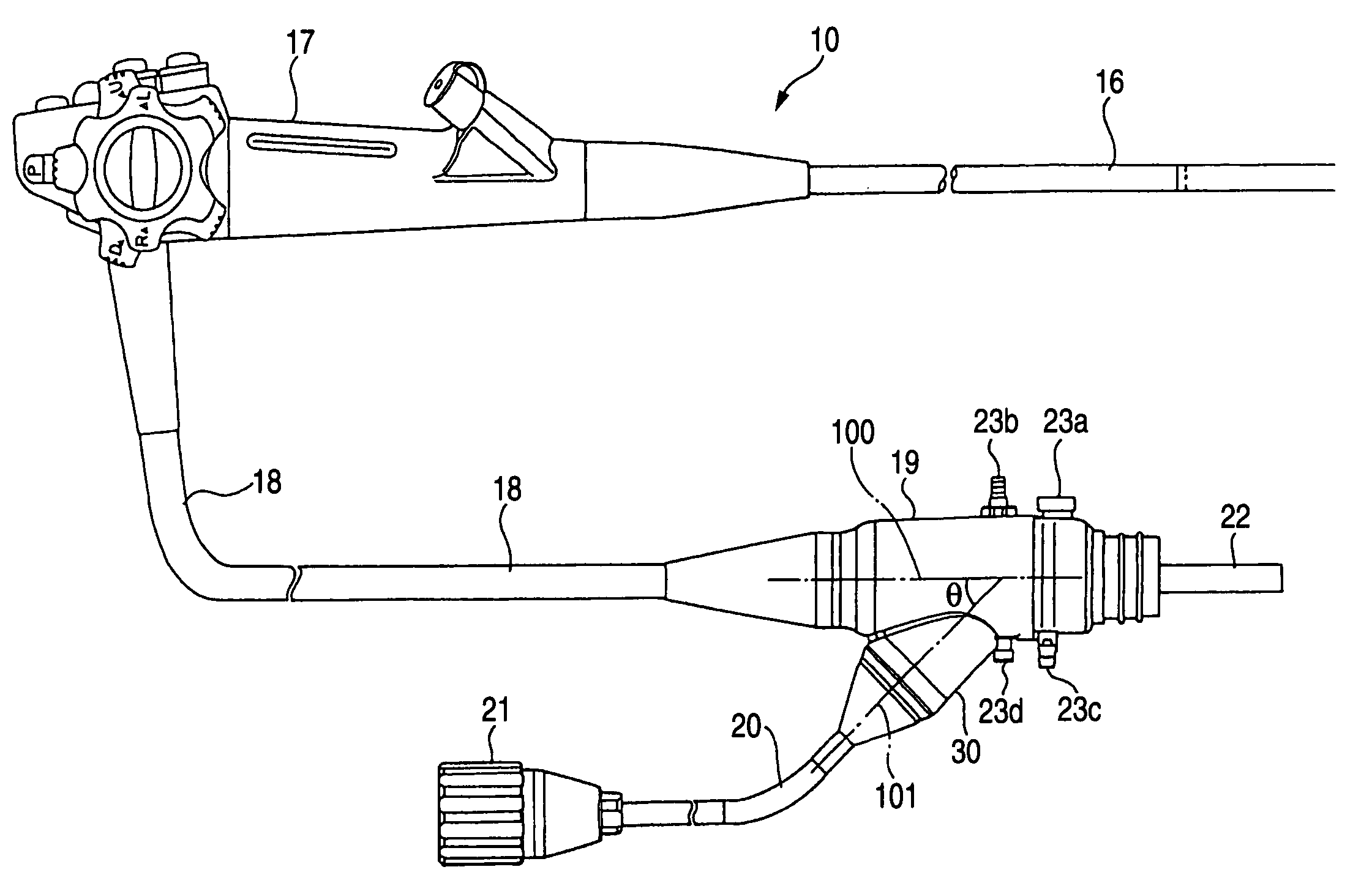
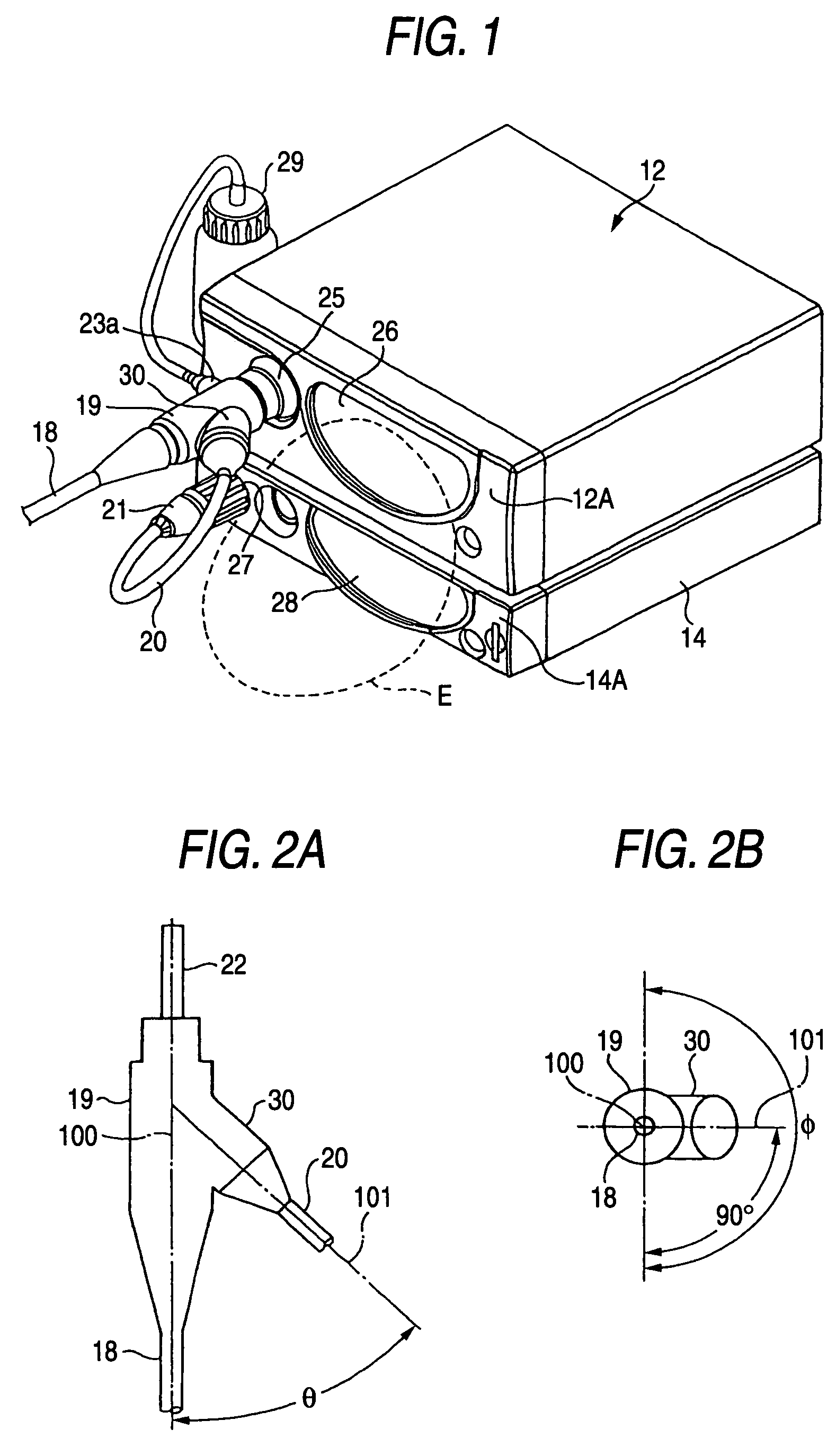
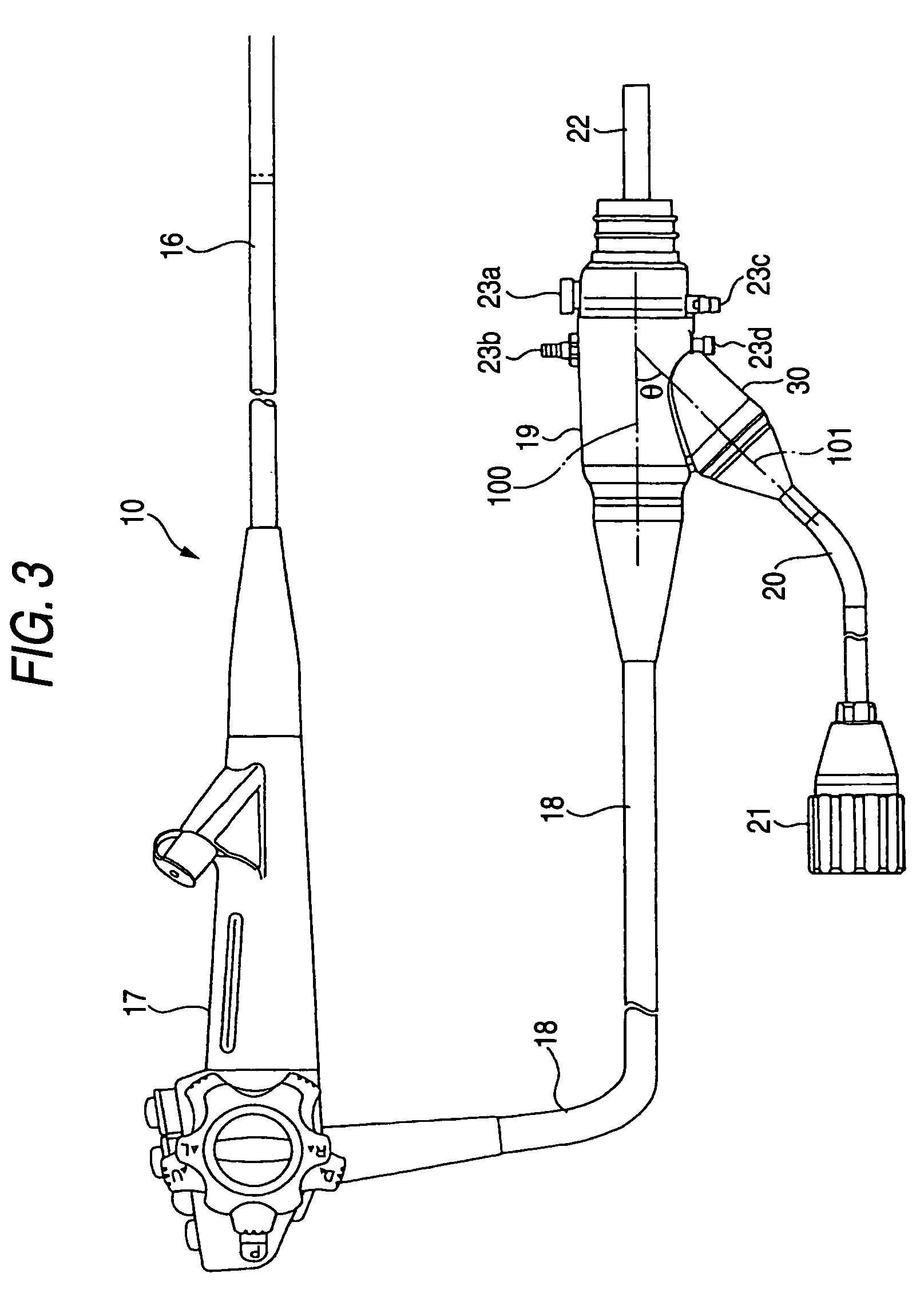
[0055]FIG. 1 through FIGS. 5A and 5B show the construction of an endoscope connector device according to an embodiment 1-1, wherein FIG. 1 is a perspective view showing a state in that the connector device is connected to a light source unit and a processor unit, and FIG. 3 is an entire construction view of an endoscope (electronic endoscope). The endoscope apparatus includes an endoscope 10 shown in FIG. 3, a light source unit 12 and a processor unit 14 shown in FIG. 1, and a monitor, etc.

[0056]In FIG. 3, the endoscope 10 includes a flexible portion 16 that is an insertion portion for a body cavity or the like and has an image pickup device on its distal end, a control portion 17 having an angle operation knob or other various switches, a light guide for guiding illumination light, a first cable 18 that includes: an electric wire for transmitting control signals and video signals; an air / water duct; and the like, the first cable 18 being for connecting these to an external unit, an...

second embodiment

[0067]FIG. 9 through FIG. 11 show a basic construction of an endoscope cable lead-out unit of the invention, wherein FIG. 9 shows an embodiment 2-1, FIG. 10 shows an embodiment 2-2, and FIG. 11 shows an embodiment 2-3. In FIG. 9, a cylindrical lead-out part outer sheath 70b is integrally formed from a synthetic resin material (hard) in the leading-out direction from an outer sheath of the main body of the light guide connector, etc., and inside the outer sheath 70b, a cylindrical frame 71 that is made of metal is arranged, and the outer circumferential edge 71a of this frame 71 is constructed so as to engage and come into contact with the base end side (cylinder bottom surface) of the outer sheath 70b. This frame 71 is provided with a presser ring 71 so as to be screwed and coupled to a screwing portion G1 at the distal end side, and the outer circumferential projection (flange portion) 72a of this presser ring 72 is engaged to be contacted with the distal end face of the outer shea...


PUM


Abstract

An endoscope connector device comprises: a first cable of an endoscope, including a light guide for supplying illumination light and an electric wire for obtaining video signals from an image pickup device; a light guide connector connected to the first cable; and a second cable of the endoscope, including the electric wire led out of the light guide connector, wherein the second cable is attached diagonally from the light guide connector at an angle θ within a range of 0°<θ<90° from a first cable side of an axial direction of the first cable.

Description

RELATED APPLICATIONS[0001]This application claims the priority of Japanese Patent Application Nos. 2004-154480 and 2004-197332, filed on May 25, 2004 and Jul. 2, 2004, respectively , which are incorporated herein by reference.BACKGROUND OF THE INVENTION[0002]1. Field of the Invention[0003]The present invention relates to an endoscope connector device, more specifically, the construction of a connector device for connecting a light guide for supplying illumination light to a light source unit and connecting an electric wire for obtaining video signals to a processor unit.[0004]The invention relates to an endoscope cable lead-out unit, more specifically, a construction of a cable lead-out part which is used for a portion where an endoscope cable including various linear members is branched, and branches an electric wire from a light guide connector for connection to a light source unit.[0005]2. Description of the Related Art[0006]FIG. 7 and FIG. 8 show the construction of the related-...

Claims


Application Information

Patent Timeline
Patent Type & Authority Patents(United States)
IPC IPC(8): A61B1/00A61B1/05A61B1/06G02B23/24H01R13/00
CPCA61B1/00114A61B1/05A61B1/06A61B1/00128A61B1/04A61B1/00124A61B1/044
Inventor HINO, KAZUHIKO
Owner FUJI PHOTO OPTICAL CO LTD
Why Eureka
Try Eureka