Surgical device

a surgical device and surgical technology, applied in the field of surgical devices, can solve the problems of increasing the difficulty of manipulating the device, and increasing the torque required to cut and staple a tissue section, so as to reduce the tendency of the upper and lower jaws to separate, reduce the torque, and reduce the distance between the upper and lower jaws

Inactive Publication Date: 2010-04-13
DORROS GERALD M D
View PDF592 Cites 1234 Cited by
  • Summary
  • Abstract
  • Description
  • Claims
  • Application Information

AI Technical Summary

Benefits of technology

[0011]By moving the cutting and stapling element from the distal end of the mechanism to the proximal end during the cutting and stapling operation, the example embodiment may reduce the tendency of the upper and lower jaws to separate during operation of the device. Specifically, by moving the cutting and stapling element from the distal end of the mechanism to the proximal end during the cutting and stapling operation, there may be a resulting reduction in the distance between the upper and lower jaws at their distal ends.
[0012]In addition, by moving the cutting and stapling element from the distal end of the mechanism to the proximal end during the cutting and stapling operation, the example embodiment m...

Problems solved by technology

One problem with the foregoing surgical devices, and in particular with the foregoing linear clamping, cutting and stapling devices such as that illustrated in FIG.
Another problem with the foregoing surgical devices, and in particular with the foregoing linear clamping, cutting and stapling devices such as that illustrated in FIG. 1, is that the devices are difficult to maneuver.
Conventional linear clamping, cutting and stapling devices such as that illustrated in FIG. 1 have an overall length which increases the difficulty in maneuvering the devic...

Method used


Image

  • Surgical device
  • Surgical device
  • Surgical device

Examples


Embodiment Construction

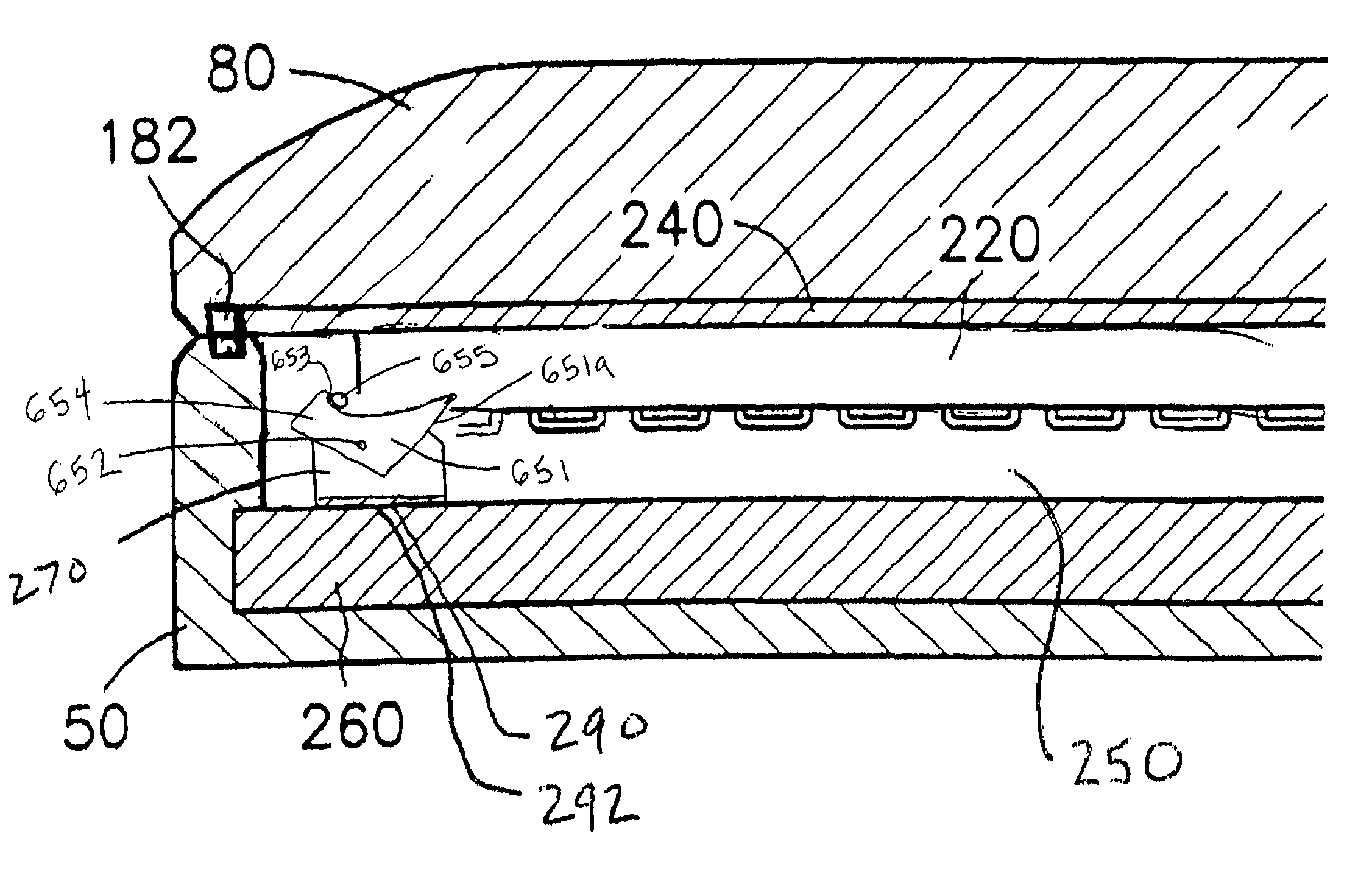
[0032]One example embodiment of a surgical device according to the present invention is illustrated in FIGS. 3 to 20. Referring to FIGS. 3 and 4, an example embodiment of the surgical device 11, e.g., a linear clamping, cutting and stapling device, is illustrated. In this embodiment, a device 11 includes a parallel separating jaw system having a lower jaw 50 in opposite correspondence to an upper jaw 80 having a proximal end 100. FIG. 3 illustrates the device 11 in a closed position, in which the lower jaw 50 and the upper jaw 80 are in contact at both their proximal and distal ends. FIG. 4 illustrates the device 11 in an open position, wherein the lower jaw 50 and the upper jaw 80 are separated. For the purposes of illustration only, FIGS. 3 to 20 illustrate the opposing jaws 50 and 80, which remain parallel relative to each other. In an alternative example embodiment, opposing jaws 50 and 80 may open and close in scissor-like fashion, wherein the proximal ends of opposing jaws 50 ...


PUM


Abstract

A surgical device includes a first jaw and a second jaw disposed in opposed correspondence with the first jaw. The second jaw is mechanically coupled to the first jaw at a proximal end opposite a distal end. A cutting element is disposed within the second jaw, and a first driver is configured to move the cutting element proximally from the distal end toward the proximal end of the second jaw to cut a section of tissue disposed between the first and second jaws. The device may also include a stapling element disposed within the second jaw. The cutting element and the stapling element may be contiguous so as to define a cutting and stapling element, such as a wedge having a blade disposed thereon. As the wedge is moved proximally from the distal end of the second jaw to the proximal end, the wedge pushes a plurality of staples against a plurality of opposing staple guides disposed in the first jaw in order to staple a section of tissue while cutting the section of tissue.

Description

CROSS-REFERENCE TO RELATED APPLICATIONS[0001]The present application incorporates herein each of the following references as fully as if set forth in their entirety: U.S. patent application Ser. No. 09 / 887,789, filed on Jun. 22, 2001; U.S. patent application Ser. No. 09 / 836,781, filed on Apr. 17, 2001; U.S. patent application Ser. No. 09 / 723,715, filed on Nov. 28, 2000; U.S. patent application Ser. No. 09 / 324,451, filed on Jun. 2, 1999; U.S. patent application Ser. No. 09 / 324,452, filed on Jun. 2, 1999; U.S. patent application Ser. No. 09 / 351,534, filed on Jul. 12, 1999 and issued as U.S. Pat. No. 6,264,087 on Jul. 24, 2001; U.S. patent application Ser. No. 09 / 510,923, filed on Feb. 22, 2000; and U.S. patent application Ser. No. 09 / 510,927, filed on Feb. 22, 2000.FIELD OF THE INVENTION[0002]The present invention relates to a surgical device. More specifically, the present invention relates to a linear clamping, cutting and stapling device for clamping, cutting and stapling tissue.BA...

Claims


Application Information

Patent Timeline
IPC IPC(8): A61B17/32A61B17/285A61B17/072A61B17/10A61B17/11A61B17/3211A61B18/00
CPCA61B17/07207A61B17/068A61B2017/07285A61B2017/07214A61B2018/1455A61B18/1445A61B17/3201
Inventor WHITMAN, MICHAEL P.BURBANK, JOHN E.
Owner DORROS GERALD M D
Why Eureka
Try Eureka