MEMS device formed inside hermetic chamber having getter film

a technology of micro electro mechanical systems and getter film, which is applied in the direction of semiconductor devices, semiconductor/solid-state device details, electrical apparatus, etc., can solve the problems of electric noise transmission through the getter film, technical obstacles in the cavity, and the problem of deep cavity, etc., to prevent the transmission of electric noise, reduce processing time, and simplify manufacturing steps

Inactive Publication Date: 2010-04-13
SUMITOMO PRECISION PROD CO LTD
View PDF8 Cites 7 Cited by
  • Summary
  • Abstract
  • Description
  • Claims
  • Application Information

AI Technical Summary

Benefits of technology

[0014]According to this MEMS device, the getter film is formed inside the hermetic chamber and connected to only one predetermined electrical potential or a ground potential, thereby preventing the potential of the getter film from so-called floating even during the operation of the MEMS device. Therefore, even in the case where the getter film is formed near an electrode of the MEMS device, the electrical potential applied to the getter is stabilized, thereby preventing the transmission of electric noise from the electrode through the getter to an electrode of a sensor or a driver. In addition, the cavity made in the glass substrate for forming the hermetic chamber can be made much shallower than that of conventional art. Therefore, less processing time, simpler manufacturing steps, and greatly reducing manufacturing costs can be achieved.
[0017]According to each of the MEMS devices recited above, the getter film formed inside the hermetic chamber is connected to only one or a plurality of predetermined electrical potentials, thereby preventing the potential of the getter film from floating even during the operation of the MEMS device. Therefore, even in the case where the getter film is formed near each of electrodes of the MEMS device, the electrical potential applied to the getter film is stabilized, thereby preventing the transmission of electric noise from the electrode via the getter to an electrode of a sensor or a driver. In addition, the cavity made in the glass substrate for forming the hermetic chamber can be made much shallower than that of conventional art. Therefore, less processing time, simpler manufacturing steps, and greatly reducing manufacturing costs can be achieved. Connecting the getter film to only a ground potential provides a more stable potential than connecting the getter film to only a predetermined electrical potential other than a ground potential, thereby further reducing electric noise transmitted to the electrodes of the sensors or the drivers, thus providing more favorable characteristics.
[0019]According to a MEMS device of the present invention, a getter film is formed inside a hermetic chamber and connected to only one predetermined electrical potential or ground potential, thereby preventing the potential of the getter film from floating even during the operation of the MEMS device. Therefore, even in the case where the getter film is formed near an electrode of the MEMS device, the electrical potential applied to the getter is stabilized, thereby preventing a transmission of electric noise from the electrode through the getter to an electrode of a sensor or a driver. In addition, the cavity made in the glass substrate for forming the hermetic chamber can be made much shallower than that of conventional art. Therefore, less processing time, simpler manufacturing steps, and greatly reducing manufacturing costs can be achieved.

Problems solved by technology

As a result of various experiments, it became apparent that a technical dilemma exists relating to a position of the getter region and the cavity depth.
In particular, in the case of shallow cavities, even, for example, in the case where a mask is used to form the getter film only on the bottom of the cavity, the location of the getter film becomes proximal to electrodes of the MEMS device, thereby resulting in electric noise transmitting via the getter film coupled capacitively to electrodes of of sensors or drivers.
Conversely, technical obstacles exist in the case where the cavity is deep, as described herewith by an example of a conventional MEMS device application.
Thus, it is difficult to maintain distances sufficient to prevent effects among members such as the getter film 73 and the primary mode sensing electrode 75.
As a result, deep cavities do not solve the problems of shallow cavities.
Moreover, deep cavities have disadvantages during manufacturing such as longer processing times and poorer process yields.

Method used


Image

  • MEMS device formed inside hermetic chamber having getter film
  • MEMS device formed inside hermetic chamber having getter film
  • MEMS device formed inside hermetic chamber having getter film

Examples


Embodiment Construction

[0040]Herewith, several exemplary embodiments of the present invention are described with reference to the drawings. In all drawings and descriptions thereof, the same reference numerals are used for similar components unless otherwise noted. Some components of exemplary embodiments are not drawn to scale. Some reference numerals are omitted for better readability in some drawings.

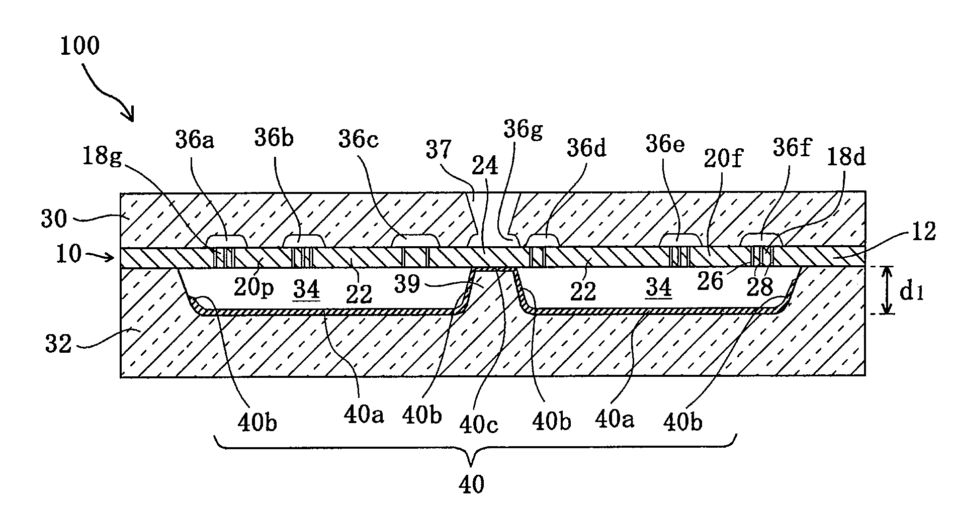
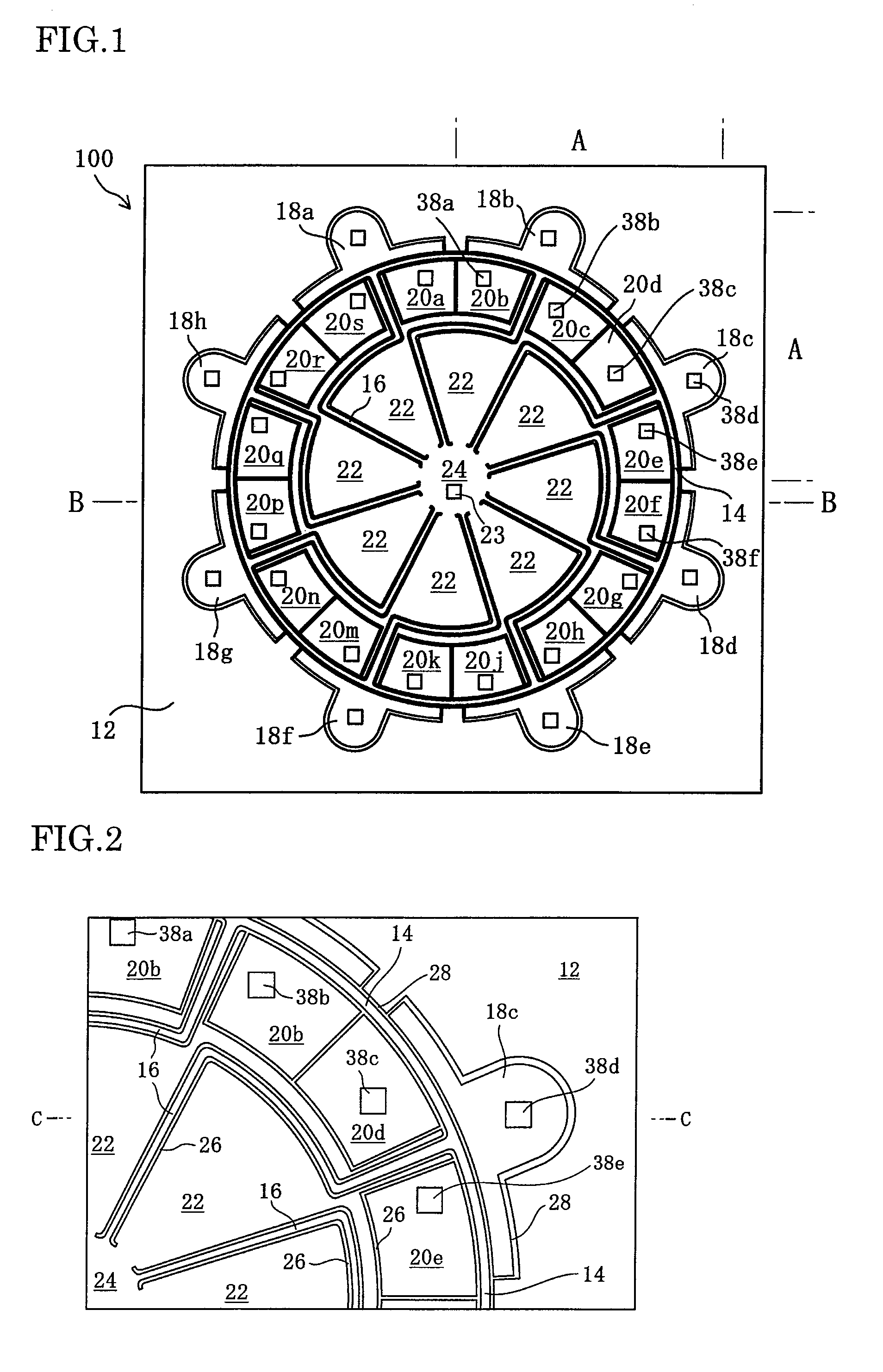
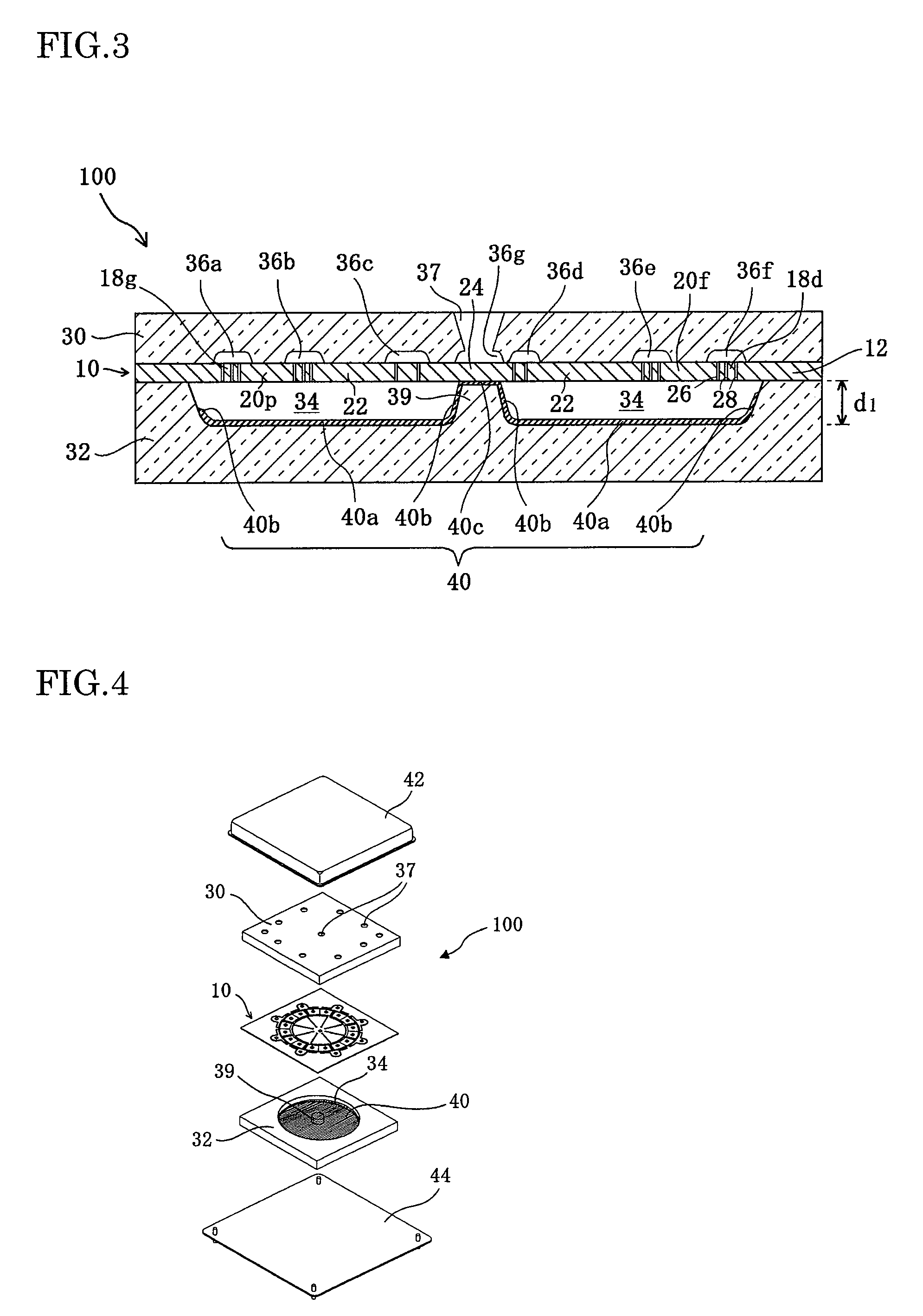
[0041]Structures performing central roles in a MEMS device, i.e., a ring or hoop-like shape resonator gyroscope 100, according to an exemplary embodiment of the present invention are illustrated in the front view of FIG. 1. FIG. 2 is a partially enlarged view of the A-A quadrant of FIG. 1. FIG. 3 is a cross-sectional view along the B-B line of FIG. 1. FIG. 4 is an exploded perspective view of the ring or hoop-like shape resonator gyroscope 100 according to this exemplary embodiment, including a package.

[0042]The MEMS device according to this exemplary embodiment illustrated in FIG. 1 through FIG. 4 is the ...


PUM


Abstract

A MEMS device including a getter film formed inside a hermetic chamber provides stable performance of the MEMS device by electrically stabilizing the getter film. The MEMS device includes a movable portion and a fixed portion formed inside the hermetic chamber. The hermetic chamber is formed by a base material of the MEMS device and glass substrates and having a cavity and cavities made therein. A part of any continuous getter film formed inside the hermetic chamber connects to only one of any one or a plurality of predetermined electrical potentials of the fixed portion and a ground potential of the fixed portion through the base material of the MEMS device.

Description

BACKGROUND OF THE INVENTION[0001]1. Field of the Invention[0002]The present invention relates to a Micro Electro Mechanical Systems (MEMS) device formed inside a hermetic chamber having a getter film.[0003]2. Description of the Related Art[0004]Silicon-based MEMS devices are rapidly progressing in a growing number of technical fields. In recent years, MEMS devices are utilized not only in micro turbines and sensors, but also in communications and medical fields. Getter technology represents a fundamental element of MEMS technology. Getters are important for stabilizing a performance of MEMS devices formed inside hermetic chambers. Improved getter technology is indispensable to an advancement of many fields, especially fields requiring miniaturization in applications such as sensors.[0005]Conventional getters are formed by vapor deposition on a bottom of a cavity made in a glass substrate. A hermetic chamber is formed, for example, by bonding silicon and glass substrates by anodic bo...

Claims


Application Information

Patent Timeline
Patent Type & Authority Patents(United States)
IPC IPC(8): H01L23/06
CPCB81B7/0038
Inventor TAKEMOTO, TSUYOSHINISHIDA, HIROSHITORAYASHIKI, OSAMUIKEDA, TAKASHIARAKI, RYUTA
Owner SUMITOMO PRECISION PROD CO LTD
Why Eureka
Try Eureka