
Motorcycle body frame structure

a technology for motorcycles and frame structures, applied in cycles, machines/engines, cycle equipment, etc., can solve the problems of increased weight, curved welding lines, and more troublesome assembly, and achieve the effect of reducing weigh

Inactive Publication Date: 2010-04-20
HONDA MOTOR CO LTD
View PDF6 Cites 10 Cited by
  • Summary
  • Abstract
  • Description
  • Claims
  • Application Information

AI Technical Summary

Benefits of technology

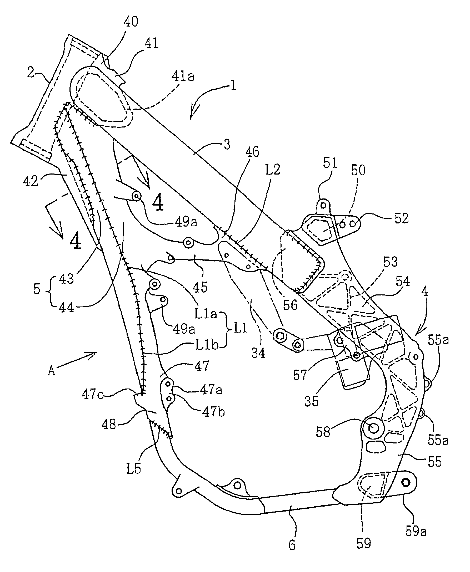
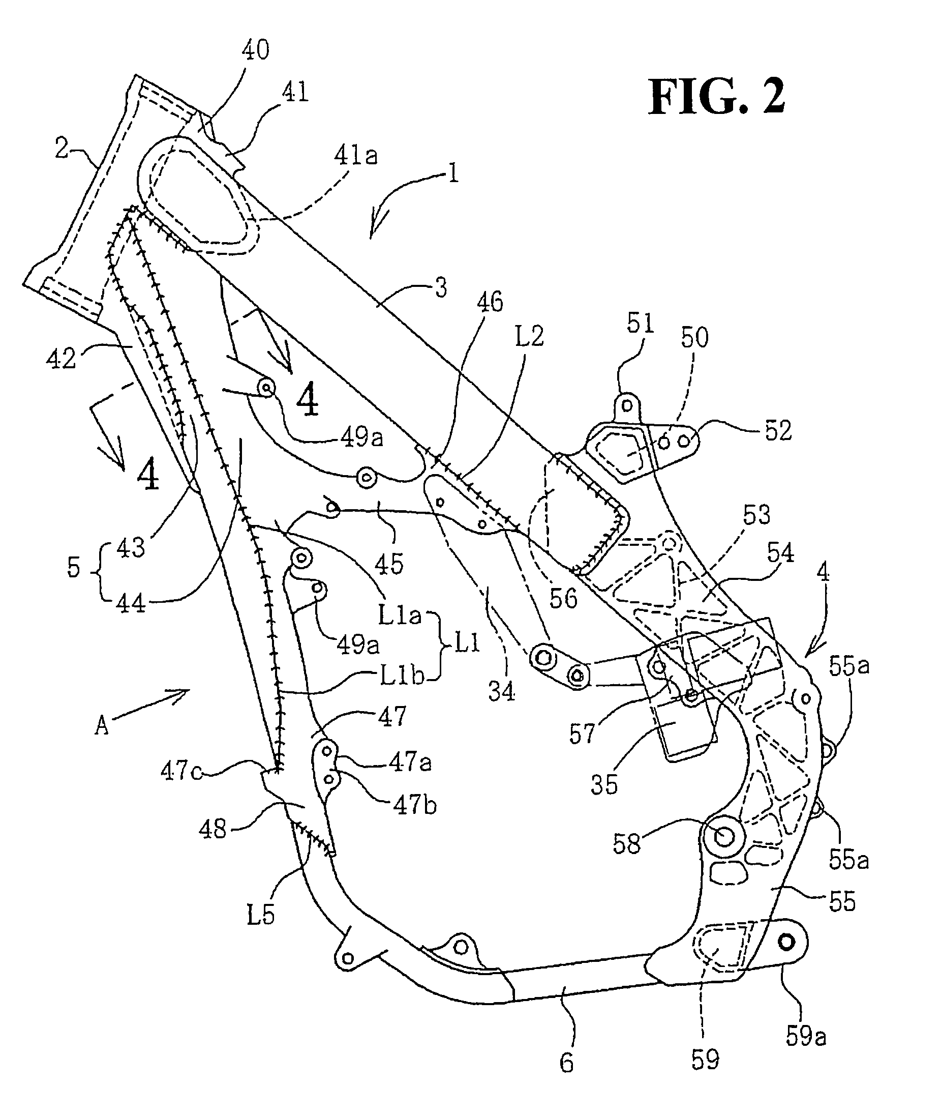
[0010]According to the first aspect of the present invention, the down frame is longitudinally divided into a down frame front portion and a down frame rear portion. The down frame front portion, which should be tough, is a tough wrought product. The down frame rear portion, which should be rigid, is formed as a rigid and easy-to-shape casting. The down frame front portion and the down frame rear portion are combined. Therefore, the features required of the down frame are achieved and the weight is reduced while the required strength and rigidity are maintained. At the same time the down frame front portion and the down frame rear portion are welded along a straight welding line along the length of the down frame, making welding simpler.
[0011]According to the second aspect of the present invention, the main joint as a connection with the main frame is formed integrally with the down frame rear portion by casting. Therefore, wider latitude in the shape of the main joint is ensured and reinforcement by a separate, welded gusset is not needed.
[0012]According to the third aspect of the present invention, the lower joint as a connection between the down frame and the lower frame is formed integrally with the down frame rear portion by casting. Therefore, wider latitude in the shape of the lower joint is ensured and reinforcement by a separate, welded gusset is not needed.

Problems solved by technology

However, the use of such a separate gusset implies that a larger number of components must be assembled and assembly is more troublesome and the weight tends to increase.
In addition, welding must be at more points during assembly; and welding must be done all around the down frame and stiffener pipe which means that the welding line is curved, and welding is complicated.

Method used


Image

  • Motorcycle body frame structure
  • Motorcycle body frame structure
  • Motorcycle body frame structure

Examples


Embodiment Construction

[0023]An embodiment will now be described with reference to the accompanying drawings, wherein the same or similar elements will be identified with the same reference numeral throughout the several views.

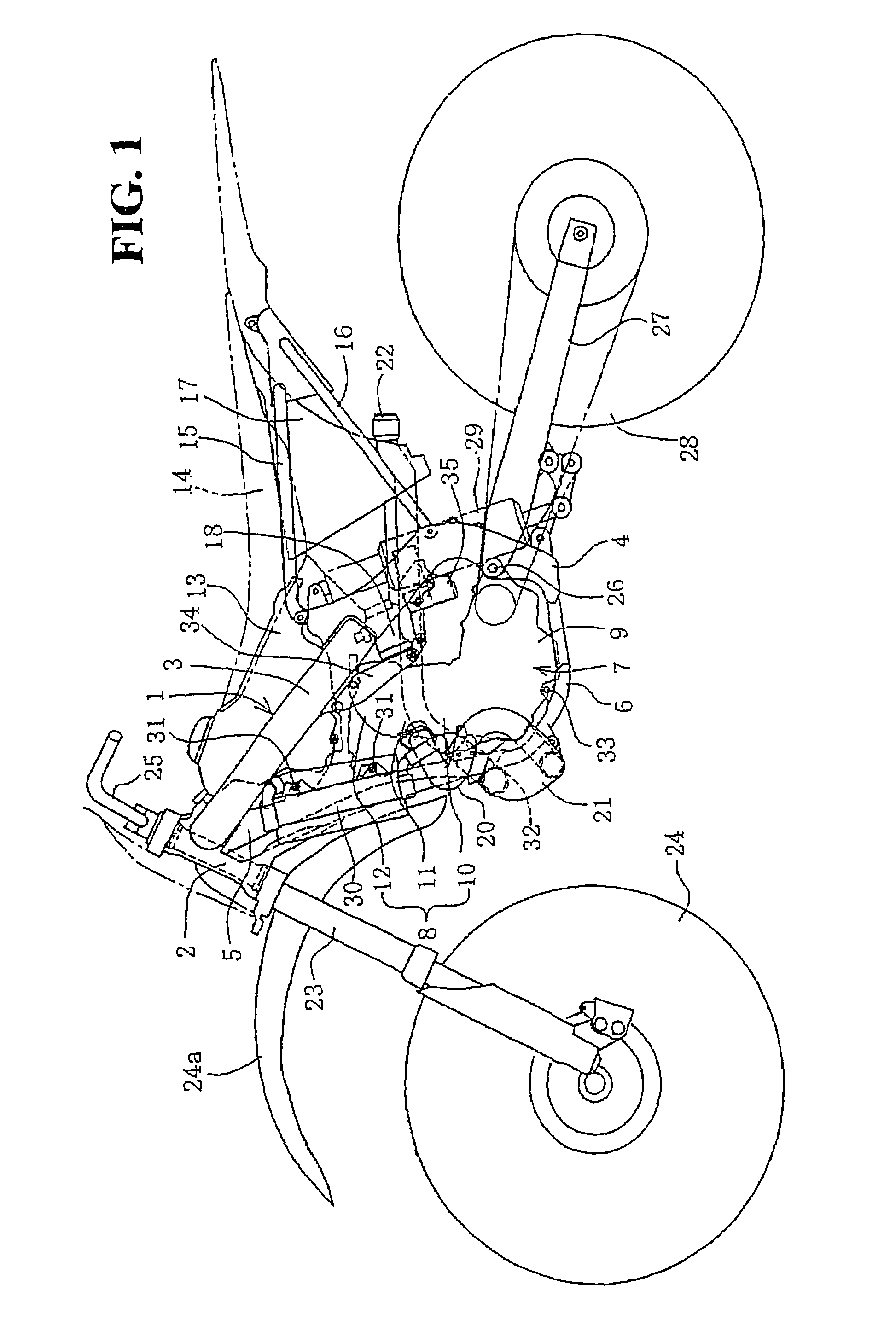
[0024]FIG. 1 is a side view of an off-road motorcycle to which the body frame structure according to this embodiment is applied. The body frame 1 of this motorcycle includes a head pipe 2, a main frame 3, a center frame 4, a down frame 5 and a lower frame 6, which are connected in a loop-like manner with an engine 7 held inside the loop. The constituent parts of the body frame 1 are each made of appropriate metal materials such as aluminum alloy. The head pipe 2 and the center frame 4 are castings. The main frame 3 and the lower frame 6 are square pipe wrought products made by extrusion molding. The down frame 5 is a combination of a wrought product and a casting and will be described in detail below.

[0025]The main frame 3 extends straight downward obliquely and backward above the e...


PUM


Abstract

To ensure that a down frame in an off-road motorcycle body frame is lightweight, rigid and easy to weld, a down frame extending downward obliquely and backward from a main frame ahead of an engine is divided along its length into a down frame front portion and a down frame rear portion. Welding joins these portions, which abut each other in the longitudinal direction. The down frame front portion is a pipe wrought product formed by extrusion molding and the down frame rear portion is a casting. Since the down frame is welded along a straight welding line extending along its length, welding is easy. Since a main joint and a lower joint are provided integrally with the down frame rear portion as a casting, a separate gusset can be omitted.

Description

CROSS-REFERENCE TO RELATED APPLICATIONS[0001]This nonprovisional application claims priority under 35 U.S.C. § 119(a) on Patent Application No. 2006-047581, filed in Japan on Feb. 23, 2006, the entirety of which is incorporated herein by reference.FIELD OF THE INVENTION[0002]The present invention relates to a motorcycle body frame structure. In particular, the present invention relates to a motorcycle body frame structure, which allows a down frame that is as lightweight as possible to be used, and makes assembly easy.DESCRIPTION OF BACKGROUND ART[0003]A publicly known motorcycle body frame includes: a head pipe; a main frame extending downward obliquely and backward from it above an engine; a down frame extending downward obliquely and backward ahead of the engine; a lower frame extending longitudinally under the engine with its front end connected with the lower end of the down frame; and a center frame connecting the rear end of the lower frame and the rear end of the main frame ...

Claims


Application Information

Patent Timeline
Patent Type & Authority Patents(United States)
IPC IPC(8): B62K11/04B62K19/12B62K19/20B62K19/28F01N13/02
CPCB62K11/04B62K19/32B62K19/20B62K19/12B62M7/02F01N13/02F01N1/08
Inventor ADACHI, EIJINOGUCHI, YUJI
Owner HONDA MOTOR CO LTD
Learn More