
Wire abnormality detecting device

a technology of abnormality detection and wires, which is applied in the direction of short-circuit testing, line-transmission details, instruments, etc., can solve the problems of inaccurate abnormality determination and inability to perform abnormality determination, and achieve the effect of accurate abnormality determination

Inactive Publication Date: 2010-04-20
MITSUBISHI ELECTRIC CORP
View PDF5 Cites 5 Cited by
  • Summary
  • Abstract
  • Description
  • Claims
  • Application Information

AI Technical Summary

Benefits of technology

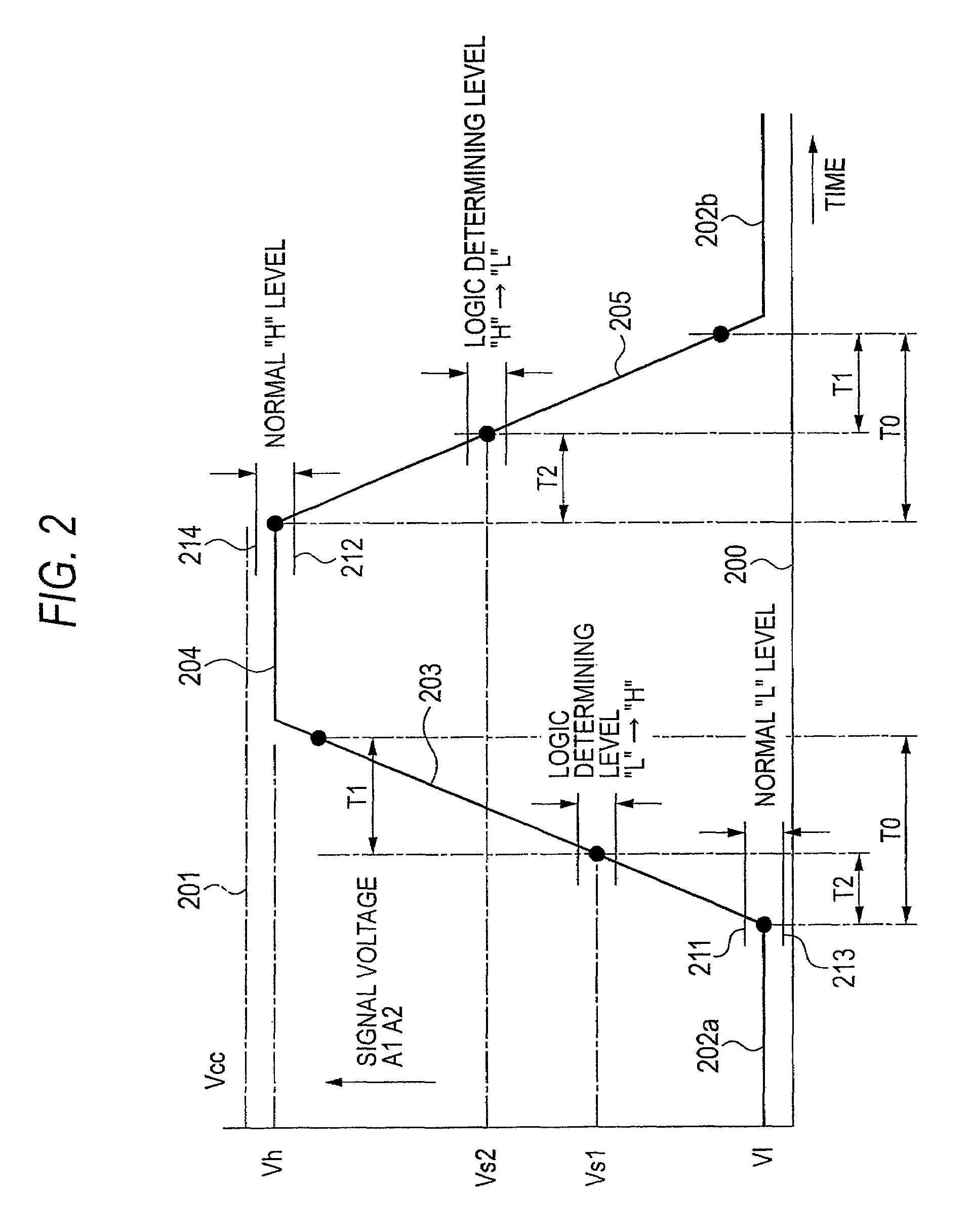
The invention is a device that detects abnormalities in a switch logic signal that is inputted to a microprocessor. The device uses an intermediate voltage state detecting means to determine when the logic of the switch logic signal exceeds certain thresholds. It also detects a transitional period when the logic level of the switch logic signal changes from low to high or from high to low. The device can accurately determine abnormalities in the signal wire caused by incomplete contact between the signal wire and power source wires or other analog signal wires. The device uses an AD converter to capture the signal voltage level of the switch logic signal and avoids mistaken determination during a process where the logic signal voltage smoothly changes due to the effects of a noise filter.

Problems solved by technology

Whereas the abnormality detecting device according to JP-A-11-64040 has the problem that abnormality determination cannot be performed in a state where the encoder is stopped, the connection defect detecting circuit according to JP-A-2000-205893 has the drawback that, although abnormality determination can be performed even in a state where the encoder is stopped, an abnormality determining circuit is disposed in the encoder and a signal wire for transmitting the determination result to the control device becomes additionally necessary.
Further, the detecting device according to JP-A-11-283456 has the problem that accurate abnormality determination cannot be performed because the output voltage of the AD converter changes due to the affects of a noise filter disposed in an input circuit of the sensor switch or the output voltage of the AD converter changes due to variations in the opening / closing timing of the sensor switch and the application timing of the pulse signal for measurement.

Method used


Image

  • Wire abnormality detecting device
  • Wire abnormality detecting device
  • Wire abnormality detecting device

Examples


embodiment 1

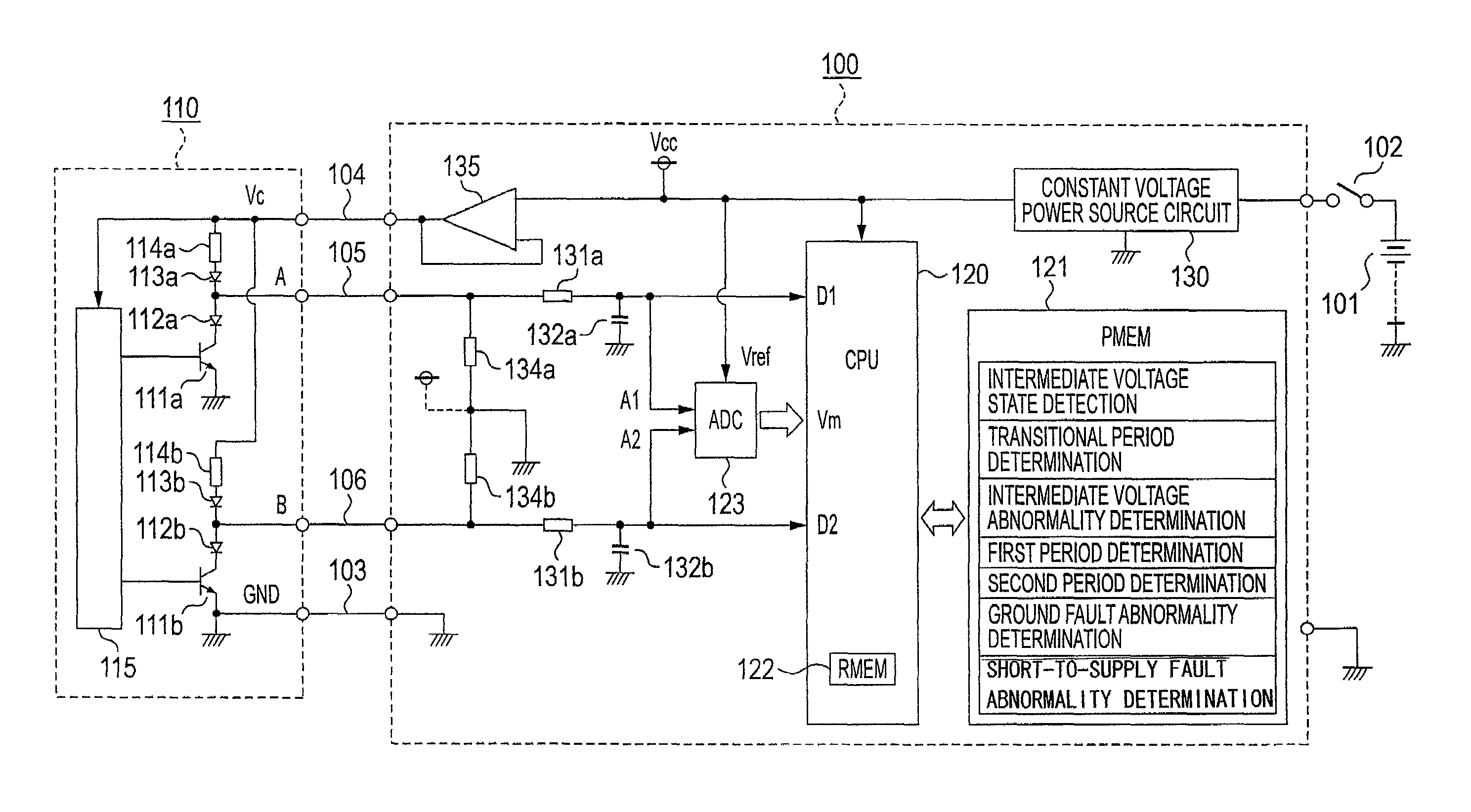
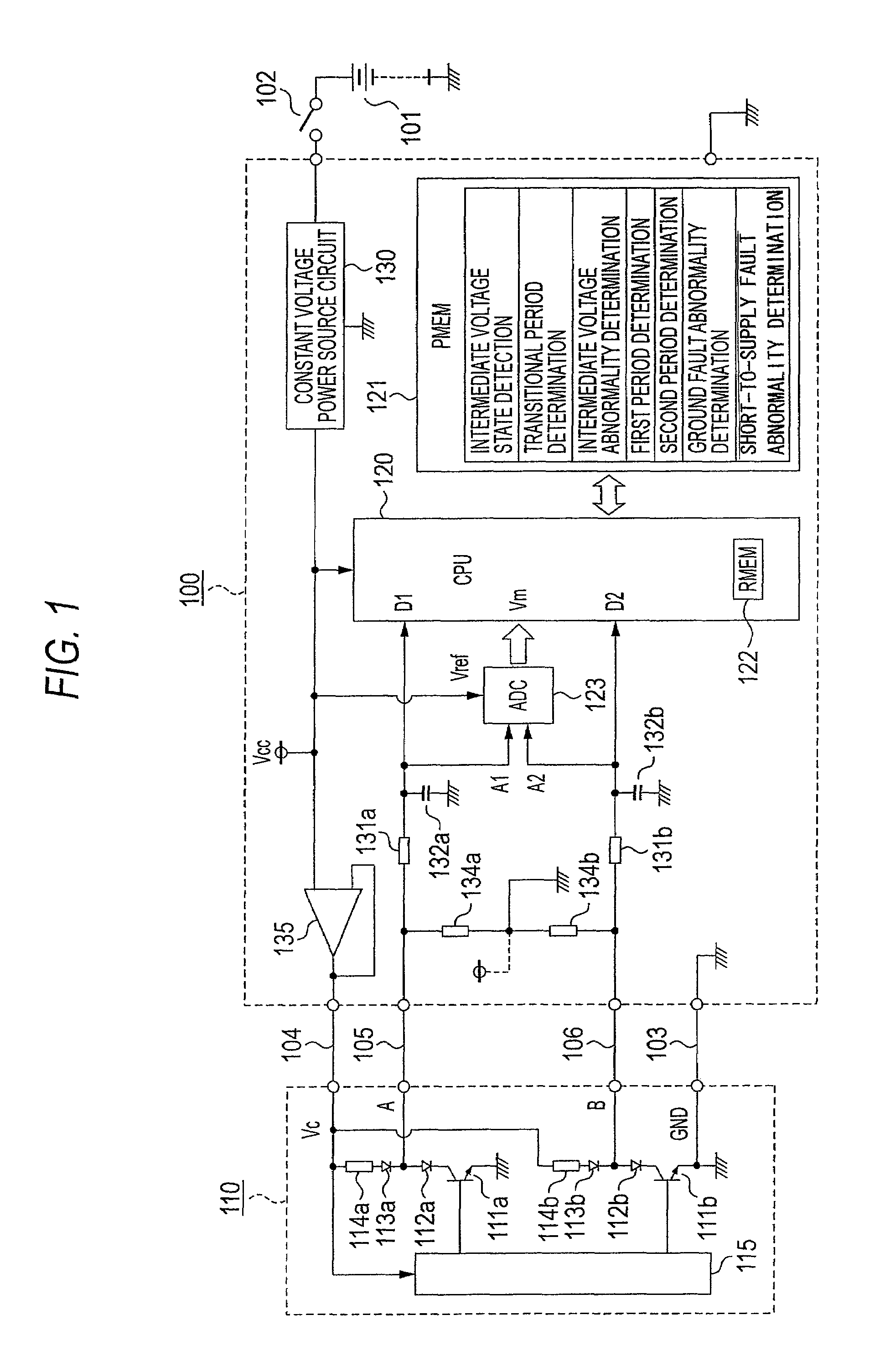
[0032]FIG. 1, which is a block circuit diagram of embodiment 1 of this invention, will be described below.

[0033]Turning now to FIG. 1, a wire abnormality detecting device 100 in actuality configures a control device of an in-vehicle engine, for example, and electricity is supplied thereto via a power source switch 102 resulting from a key switch or the like from a variable power source 101 that is an in-vehicle battery, for example, whose power source voltage varies.

[0034]Numerous input / output signals are connected to the in-vehicle engine control device, and some of those input signals become targets of wire abnormality detection; for example, a rotary encoder 110 is connected to the wire abnormality detecting device 100 that is an in-vehicle engine control device disposed with a wire abnormality detecting function.

[0035]The rotary encoder 110 receives the supply of a constant drive voltage Vc of DC 5 V, for example, via a negative power source line 103 and a positive power source ...

embodiment 2

[0139]FIG. 7, which shows a block circuit diagram of embodiment 2 of this invention, will be described below.

[0140]Turning now to FIG. 7, a wire abnormality detecting device 700 in actuality configures a control device of an in-vehicle engine, for example, and electricity is supplied thereto via a power source switch 702 resulting from a key switch or the like from a variable power source 701 that is an in-vehicle battery, for example, whose power source voltage varies.

[0141]Numerous input / output signals are connected to the in-vehicle engine control device, and some of those input signals become targets of wire abnormality detection; for example, a sensor switch group 710 is connected to the wire abnormality detecting device 700 that is an in-vehicle engine control device disposed with a wire abnormality detecting function.

[0142]The sensor switch group 710 receives the supply of a variable power source voltage Vb via a negative power source line 703 and a positive power source line...


PUM


Abstract

A sensor switch 111a connected to a constant voltage Vc via a breeder resistor 114a and dropper diodes 112a and 113a is connected to a microprocessor 120 that configures a wire abnormality detecting device 100, and the electric potential of the connection point between the dropper diodes 112a and 113a is inputted to the microprocessor 120 as a switch logic signal D1 via a signal wire 105 and a series resistor 131a. The signal voltage level of the switch logic signal D1 is inputted to the microprocessor 120 via an AD converter 123, and the microprocessor 120 cooperates with a program memory 121 to perform a determination of whether or not the signal voltage is in an abnormal intermediate voltage state. However, during a transitional period when the switch logic signal is changing between high and low, mistaken determination is prevented by avoiding abnormality determination.

Description

BACKGROUND OF THE INVENTION[0001]1. Field of the Invention[0002]The present invention relates to the improvement of a wire abnormality detecting device that is installed as a partial function in an in-vehicle electronic control device such as an engine control device or a transmission control device, for example, and in particular to a wire abnormality detecting device that detects an abnormality in a signal wire of a sensor switch that is inputted as a switch logic signal with respect to a microprocessor.[0003]2. Description of the Related Art[0004]Sensor switches serving as various switch logic signals are connected to an in-vehicle electronic control device and, from the standpoint of safety control of the vehicle, detecting an abnormality such as a wire breakage abnormality of a signal wire, a ground fault abnormality that is a short circuit abnormality with a negative power source wire, and a short-to-supply fault abnormality that is a short circuit abnormality with a positive ...

Claims


Application Information

Patent Timeline
Patent Type & Authority Patents(United States)
IPC IPC(8): G01R31/02G01R31/58
CPCG01R31/024G01R31/007G01R31/2829G01R31/52G01R31/58
Inventor TSUNEKAZU, SHOSOHASHIMOTO, KOJIEGUCHI, DAISUKE
Owner MITSUBISHI ELECTRIC CORP
Learn More