
System and method for producing a three-dimensional model

a three-dimensional model and system technology, applied in the field of fabrication implants to replace bony structures, can solve the problems of not providing a mechanism, limited the usefulness of their methods and implants to the relevant field, and the implant may not be the so as to achieve the effect of correct shape and/or size and implant drop

Inactive Publication Date: 2010-04-20
OSTEOPLASTICS
View PDF16 Cites 137 Cited by
  • Summary
  • Abstract
  • Description
  • Claims
  • Application Information

AI Technical Summary

Benefits of technology

[0016]Another advantage of the present invention is that an implant having substantially the correct shape and / or size is created.
[0017]Still further advantages of the present invention will become apparent to those of ordinary skill in the art upon reading and understanding the following detailed description of the preferred embodiments.

Problems solved by technology

Each of these patents, however, suffer from many disadvantages that have collectively limited the usefulness of their methods and implants to the relevant field.
The primary disadvantage of these methods is that they do not provide a mechanism for ensuring that the implant will be a “drop in” replacement for the missing bony material.
More specifically, the implant may not be the correct shape and / or size and, therefore, not properly fit the prosthetic into the patient.
Without a proper fit, there can be a wide variety of complications with the implant, including complications that arise during the surgical process as well as during the healing process.
Ultimately, these complications may result in the patient experiencing pain, disuse, atrophy, implant or surrounding structure mechanical failure, and / or the body rejecting the implant.
Thus, it is a critical disadvantage of these prior art systems and methods that they do not provide the ability to ensure a custom fit, “drop in” replacement for the missing body segment.

Method used


Image

  • System and method for producing a three-dimensional model
  • System and method for producing a three-dimensional model
  • System and method for producing a three-dimensional model

Examples


Embodiment Construction

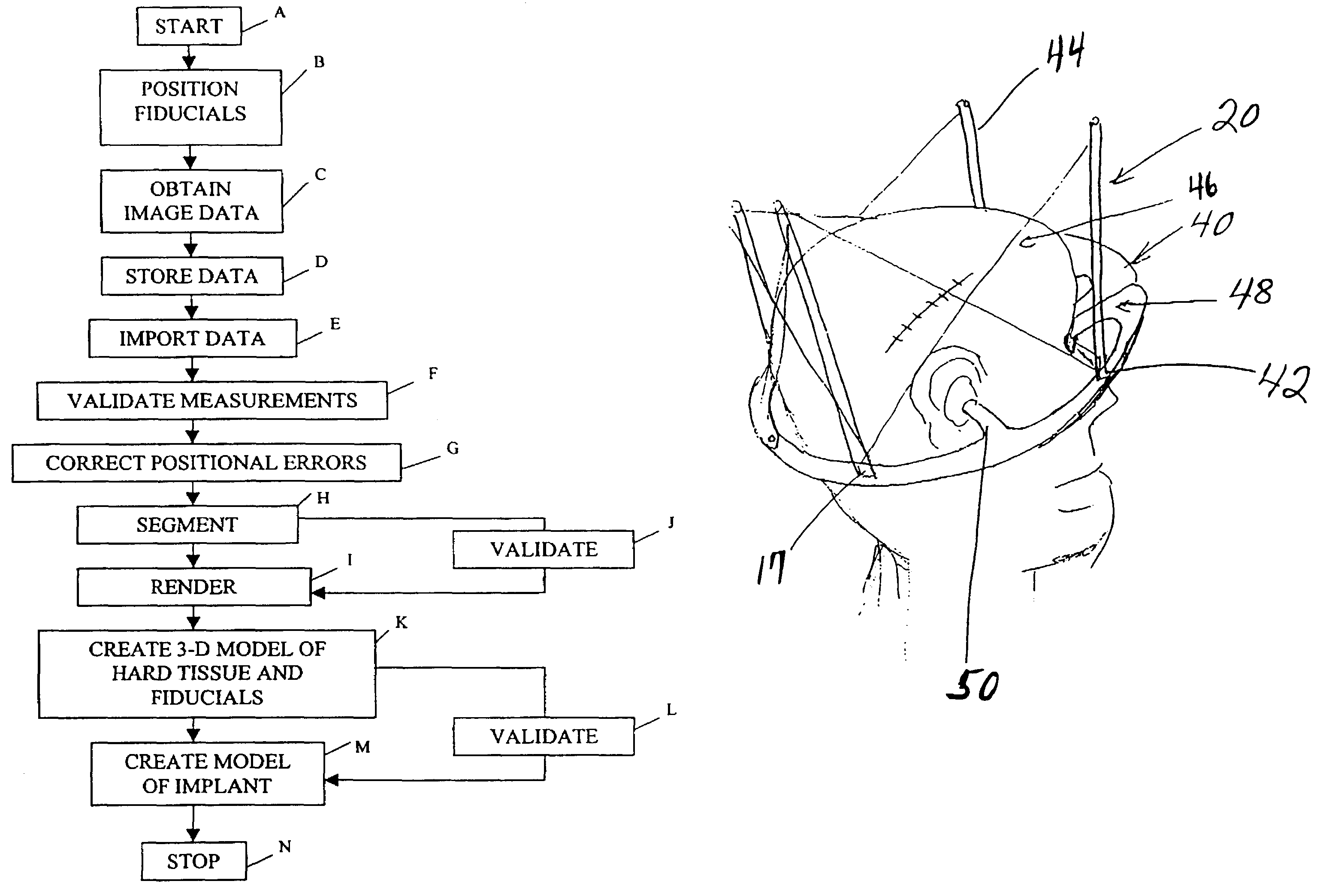
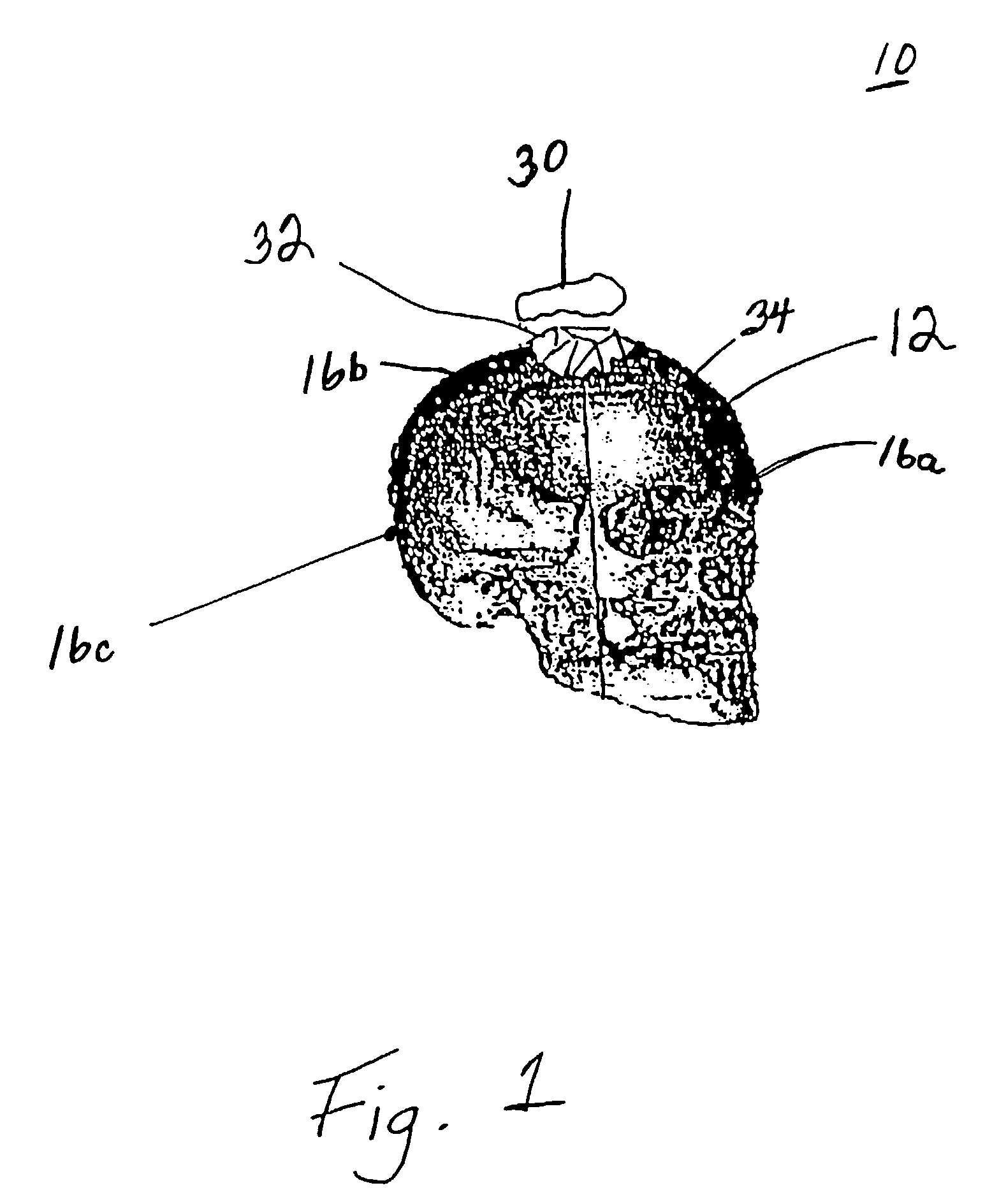
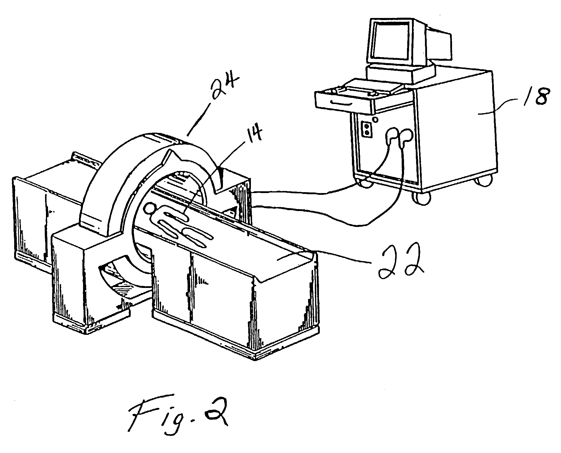
[0024]With reference to FIGS. 1-3, a method for creating a 3-dimensional model 10 of a hard tissue of interest 12, which is included within a subject 14, and a plurality of fiducials 16a, 16b, 16c begins in a step A. The hard tissue of interest 12 may include bony structure (e.g., a skull) in the subject 14. The frameless approach to creating fiduciary distances is to position fiducial markers 16, in a step B, in a fixed relationship to the subject 14. In the preferred embodiment (i.e., a frameless technique), the fiducials 16 are spherical markers (e.g., about 1.5 mm thick and including a lead material) placed (adhesed) around a defect 32 on the subject 14. In the preferred embodiment, three (3) fiducials 16 are used. However, additional fiducials may be used, especially if there is any concern that muscles of the subject's 14 facial expression might twitch the marker site during a scan. Alternatively, with reference to FIG. 4, which will be discussed in more detail below, fiducial...


PUM


Abstract

A shape of a medical device to be implanted into a subject is verified by acquiring a plurality of inter-fiduciary marker dimensions from the subject. Three-dimensional image data of the markers and a tissue of interest, included in the subject, is obtained. Respective measurements between the fiduciary markers around the subject and in the image data are confirmed. The tissue of interest and the fiduciary markers are identified in the image data. Points of the tissue of interest and the fiduciary markers are rendered as a 3-dimensional surface representation. A 3-dimensional model of the tissue of interest and the fiduciary markers is generated as a function of the surface representation. A shape of the medical device to be implanted into the subject is determined as a function of the 3-dimensional model.

Description

[0001]This application claims the benefit of U.S. Provisional Application No. 60 / 163,323, filed Nov. 3, 1999.BACKGROUND OF THE INVENTION[0002]The present invention relates to fabricating implants to replace bony structures. More specifically, the invention relates to a system and methodology for fabricating a “drop in” (i.e., the prosthetic's fit is prefabricated taking into account all of the subject's anatomy surrounding the site where it will sit) quality replacement for a particular segment of missing bony structure, in which the implant fits precisely replacing the contours of the missing segment and thus minimizes length and complications during the surgical procedure to install the implant, and subsequently facilitates the healing process. Current standard of care is to mass produce a “shape” that matches the patient's anatomy in only few dimensions that are obtained by external measurements. Often parts of the patient's anatomy must be removed to get a good fit. Anything els...

Claims


Application Information

Patent Timeline
Patent Type & Authority Patents(United States)
IPC IPC(8): A61B5/05G06T17/00
CPCG06T17/00B33Y80/00
Inventor DEAN, HOWARD DAVID
Owner OSTEOPLASTICS
Learn More