Blade driving assembly for an adjustable hair clipper

a driving assembly and adjustable technology, applied in the direction of metal working devices, etc., can solve the problems of difficult to ensure difficult relatively expensive torsion springs, etc., to achieve accurate adjustment of cut length of hair, simple structure, and low manufacturing cost

Inactive Publication Date: 2010-04-27
SPECIALIFE INDS
View PDF8 Cites 28 Cited by
  • Summary
  • Abstract
  • Description
  • Claims
  • Application Information

AI Technical Summary

Benefits of technology

[0004]In view of the aforesaid disadvantages now present in the prior art, the object of the present invention is to provide a blade driving assembly for an adjustable hair clipper which ensures accurate adjustment of cut length of hairs yet is of simple structure and low manufacturing costs.
[0006]The connecting means of the spring holder comprises a driving shaft, a pair of through holes arranged at the front end of the spring holder for receiving a middle portion of the driving shaft, a locking tab with its front end abutting against an underside of the driving shaft and its rear end fastened to the spring holder at a position rear to the pair of through holes, and a pair of hooked sections disposed at the rear end of the movable blade holder for receiving the driving shaft with the pair of through holes disposed therebetween in a way which allows the movable blade holder to move in a lateral reciprocating manner along the driving shaft.

Problems solved by technology

However, the use of torsion spring to drive the forward and backward movements of the movable blade holder makes it very difficult to achieve accurate adjustment of cut length of hairs.
To achieve accurate adjustment of cut length of hairs, one possible way is to use high quality torsion springs with consistent tensility but such torsion springs are relatively expensive.
Furthermore, torsion springs are easily susceptible to deformation, fatigue and other problems after prolonged usage, and so it would be difficult for conventional hair clippers to ensure accurate adjustment of the cut length of hairs after a period of time.

Method used


Image

  • Blade driving assembly for an adjustable hair clipper
  • Blade driving assembly for an adjustable hair clipper
  • Blade driving assembly for an adjustable hair clipper

Examples


Embodiment Construction

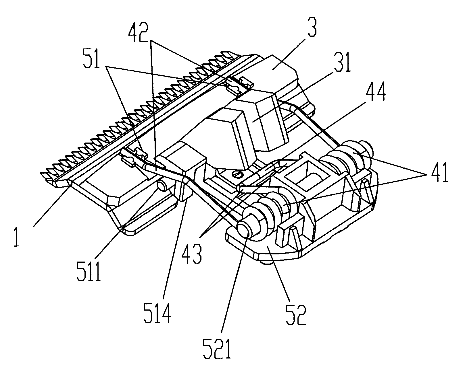
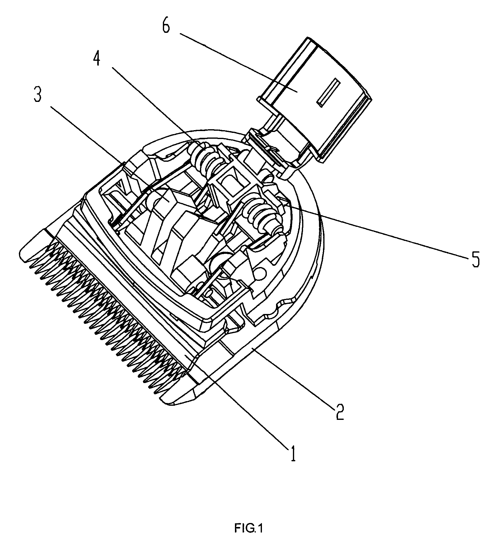
[0022]The present invention is further described in detail with the following embodiment and the accompanying drawings. As illustrated in FIG. 1, the blade driving assembly for an adjustable hair clipper of the present invention has a movable blade 1 driven by the blade driving assembly to reciprocate laterally relative to a stationary blade 2 in an operative condition. The blade driving assembly comprises a movable blade holder 3, a spring means 4, a spring holder 5 and a push lever 6.

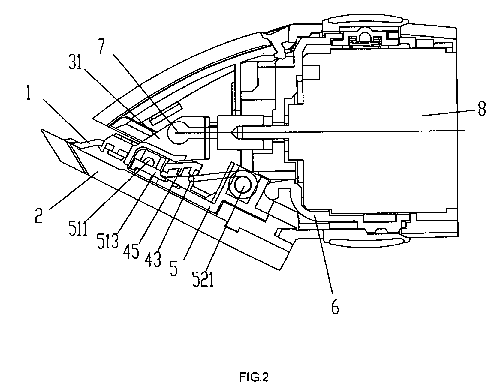
[0023]As illustrated in FIGS. 1 to 3, the movable blade holder 3 is fastened to the movable blade 1 and disposed with a fastening slot 31. The fastening slot 31 engages with an eccentric pin 7 driven by a motor 8 to drive the movable blade holder 3 and the movable blade 1 to move in a lateral reciprocating manner.

[0024]As illustrated in FIGS. 2 to 4, in this embodiment, the spring means 4 is a torsion spring disposed with a pair coiled portions 41 secured on the spring holder 5. Two segments 42 extend...


PUM


Abstract

A blade driving assembly for an adjustable hair clipper of the present invention comprises a movable blade holder, a spring, a spring holder and a push lever. The spring is disposed with a coiled portion secured on the spring holder, a first portion which exerts pressure upon the movable blade holder to bias the movable blade towards the stationary blade and a second portion which biases the spring holder towards a retracted position. The push lever is driven to move forward or backward by an external force, and a front end of the push lever abuts against the rear end of the spring holder in such a way to push the spring holder forward when the push lever is driven forward, and when the push lever is driven backward, the spring holder is biased by the spring to retract until the rear end thereof abuts against the push lever.

Description

BACKGROUND OF THE INVENTION[0001]The present invention relates to a blade driving assembly for an adjustable hair clipper and more particularly pertains blade driving assembly for driving the movable blade of a hair clipper to move laterally relative to the stationary blade in a reciprocating manner to cut the hairs and longitudinally to adjust the cut length of hairs.[0002]Conventional hair clippers are usually provided with a movable blade driven by a blade driving assembly to reciprocate laterally relative to a stationary blade in an operative condition. The movable blade is fastened to a movable blade holder and the movable blade holder is provided with a fastening slot which engages with an eccentric pin driven by a motor to drive the movable blade holder and the movable blade to move in a lateral reciprocating manner. A torsion spring is usually provided to exert pressure upon the movable blade holder to bias the movable blade towards the stationary blade on one hand, and to c...

Claims


Application Information

Patent Timeline
Patent Type & Authority Patents(United States)
IPC IPC(8): B26B19/20
CPCB26B19/205B26B19/3846B26B19/28
Inventor LAU, TUNG YAN
Owner SPECIALIFE INDS
Why Eureka
Try Eureka