Cogeneration method and device using a gas turbine comprising a post-combustion chamber

Inactive Publication Date: 2010-04-27
INST FR DU PETROLE
View PDF12 Cites 28 Cited by
  • Summary
  • Abstract
  • Description
  • Claims
  • Application Information

AI Technical Summary

Benefits of technology

[0012](c) at least some of the hot gases obtained by the pressurized

Problems solved by technology

The drawback of such a method is that the temperature of the hot gases is insufficient to heat industrial facilities operating at relatively high temperatures, for example greater than 500° C.
Moreover, direct utilization of the hot gases leaving the gas turbine is difficult since the pressure loss at the outlet of the gas turbine must remain very low, since these gases are leaving at a pressure close to atmospheric pressure and any pressure loss, even a relatively small loss, greatly interferes with gas turbine performance.
The proposal has also been m

Method used


Image

  • Cogeneration method and device using a gas turbine comprising a post-combustion chamber
  • Cogeneration method and device using a gas turbine comprising a post-combustion chamber
  • Cogeneration method and device using a gas turbine comprising a post-combustion chamber

Examples


Embodiment Construction

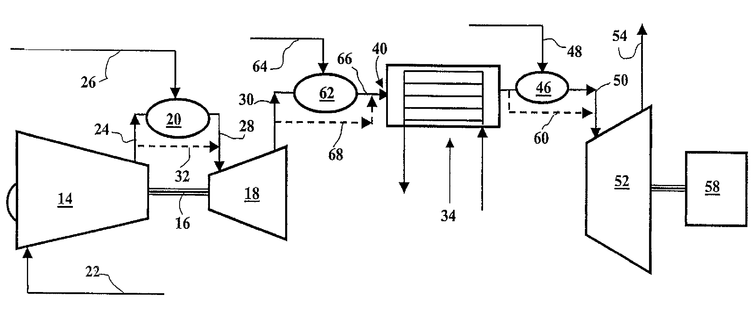
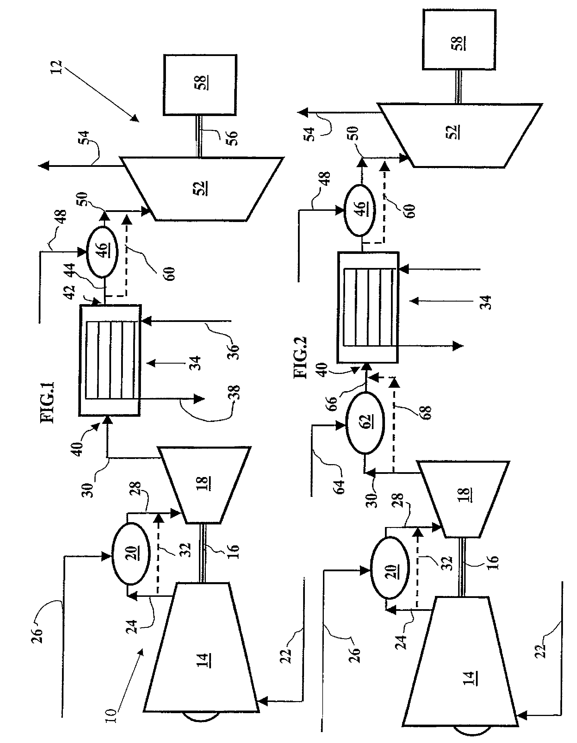
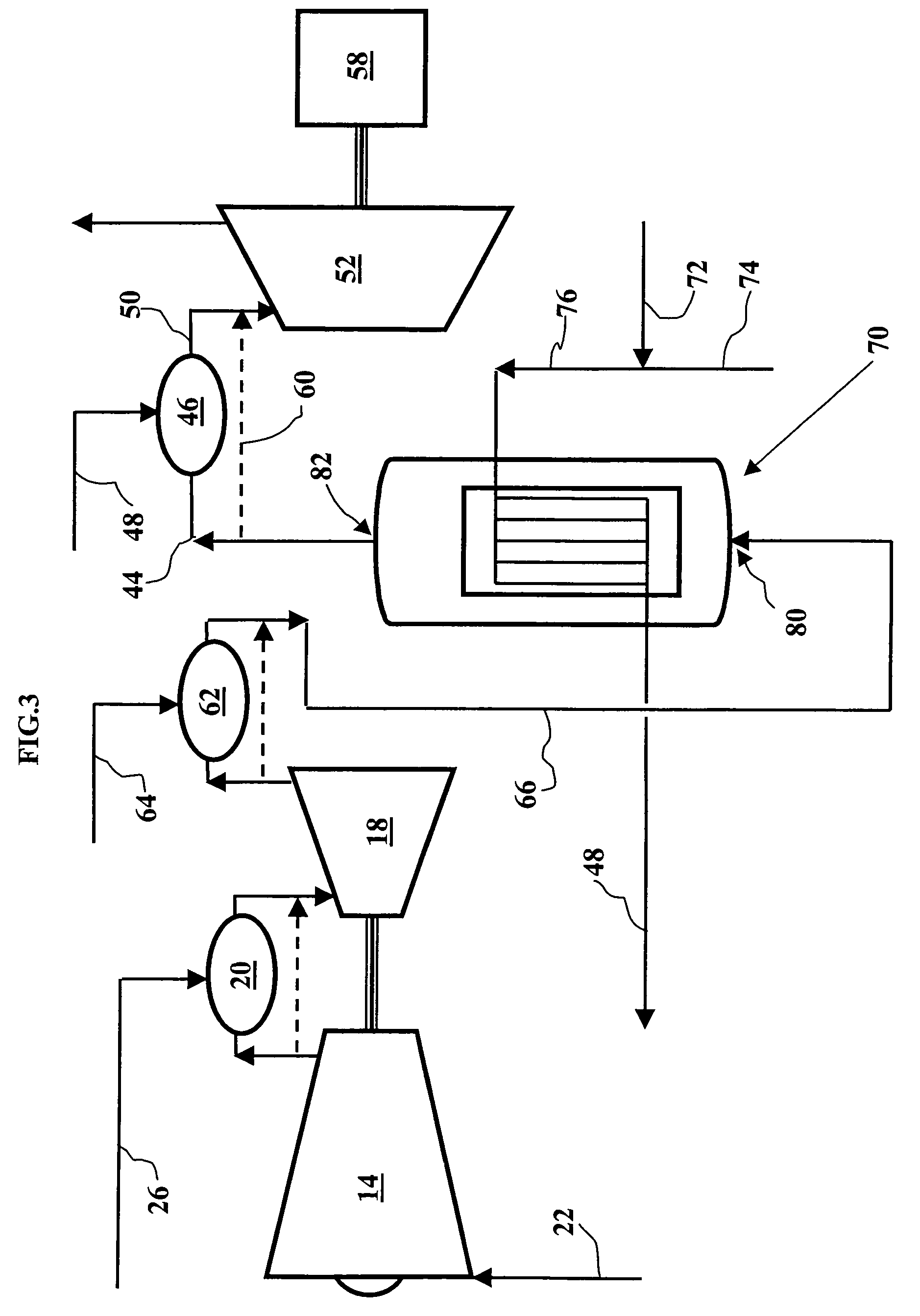
[0032]The example in FIG. 1 shows a device with a particular type of gas turbine known as a double-shaft turbine.

[0033]In this configuration, the gas turbine has a compression-expansion cell 10 in which a first expansion step compresses the combustion air and an expansion cell 12 with a second expansion step for generating mechanical and / or electrical power.

[0034]The expansion-compression cell 10 includes a compressor 14 connected by a shaft 16 to a first expansion section with an expansion turbine 18 and a combustion chamber 20. A fluid containing oxygen, generally outside air, is admitted through a pipe 22 into the compressor 14 which it leaves in the compressed state through a pipe 24. The combustion chamber 20 is supplied with fuel, for example natural gas, through a pipe 26 and with a combustion agent which, in the present case, is wholly or partially compressed air carried by pipe 24. The hot gases coming from combustion of the fuel mixture with compressed air in combustion ch...


PUM


Abstract

A cogeneration method and device by turbine, particularly by gas turbine, uses a compression section, at least one expansion section, and a combustion chamber. A combustion agent including oxygen is compressed in the compression section; in the combustion chamber, one combustion step is carried out under pressure with a mixture of combustion agent compressed with a fuel; at least some of the hot gases obtained by pressurized combustion are used to effect an exchange with an external facility; and at least one postcombustion step is carried out of a mixture of hot gases coming from combustion with a fuel, prior to the exchange, and at least one other postcombustion step of a mixture of hot gases, coming from the exchange, with a fuel, in order to obtain hot gases that are sent to the expansion section.

Description

BACKGROUND OF THE INVENTION[0001]The present invention relates to a method and a device for cogenerating heat and work.[0002]It relates in particular to a cogeneration method implemented by means of a turbine, particularly a gas turbine.[0003]More specifically, the method consists of using the hot combustion gases generated by the gas turbine to exchange heat with an industrial facility to produce an endothermic reaction for example.[0004]Prior cogeneration methods consisted of using the hot combustion gases leaving the turbine, which are generally at a pressure close to atmospheric pressure, to generate for example steam under pressure by heat exchange produced in an exchanger traversed by these hot gases and through which a fluid such as water flows. These systems can feed a steam distribution system that can supply various industrial facilities such as the heating of distillation column reboilers.[0005]The drawback of such a method is that the temperature of the hot gases is insu...

Claims


Application Information

Patent Timeline
IPC IPC(8): F02C1/06F02C6/00F02C6/18
CPCF02C6/00F02C6/003F02C6/18F02C6/006Y02E20/14
Inventor MINKKINEN, ARILEBAS, ETIENNEROJEY, ALEXANDRE
Owner INST FR DU PETROLE
Why Eureka
Try Eureka