Bracket and head rail assembly

a head rail and bracket technology, applied in the direction of sliding/moving grilles, door/window protective devices, curtain suspension devices, etc., can solve the problems of excessive volume occupied by the assembly and the excessive height of the head rail, and achieve the effect of simple structur

Inactive Publication Date: 2010-04-27
NIEN MADE ENTERPRISE CO LTD
View PDF16 Cites 14 Cited by
  • Summary
  • Abstract
  • Description
  • Claims
  • Application Information

AI Technical Summary

Benefits of technology

[0006]In view of the above, the present invention provides a bracket and head rail assembly, wherein a bracket has a simple structure and a head rail has a small height, and furthermore, the head rail is locked in the bracket in dual directions, such that both two side surfaces of the head rail may be served as the front side of the assembly, thus achieving diversified assembling modes.
[0008]To sum up, as for the bracket and head rail assembly provided by the present invention, since a track-shaped gripping part is formed on one side surface of the head rail to grip with the bracket, the structure of the head rail is simplified and designed into a thin configuration. Therefore, when the head rail is mounted to the bracket, the head rail is gripped into the bracket in any direction, and the different exteriors or curve designs of different side surfaces of the head rail provides diversified assembling selections. The body and the fastener of the bracket are integrated into one piece and formed by bending and processing, and both are simply assembled and designed into a thin configuration, thus, the simple structure of the bracket further reduces the manufacturing and assembly costs.

Problems solved by technology

However, as for the head rail and the mounting bracket assembly disclosed in U.S. Pat. No. 6,293,330, the first and second lips of the head rail are disposed into the head rail, such that the head rail is too high.
Such design also causes the interlocking element to have a large volume, thus, the volume occupied by the assembly is accordingly too large.

Method used


Image

  • Bracket and head rail assembly
  • Bracket and head rail assembly
  • Bracket and head rail assembly

Examples


Embodiment Construction

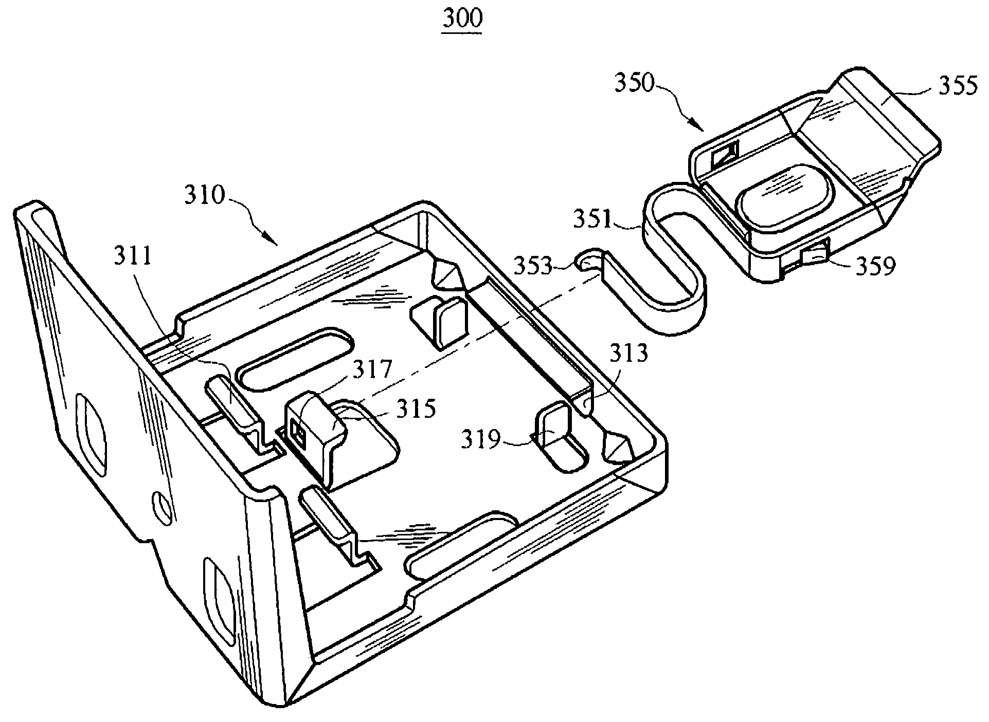
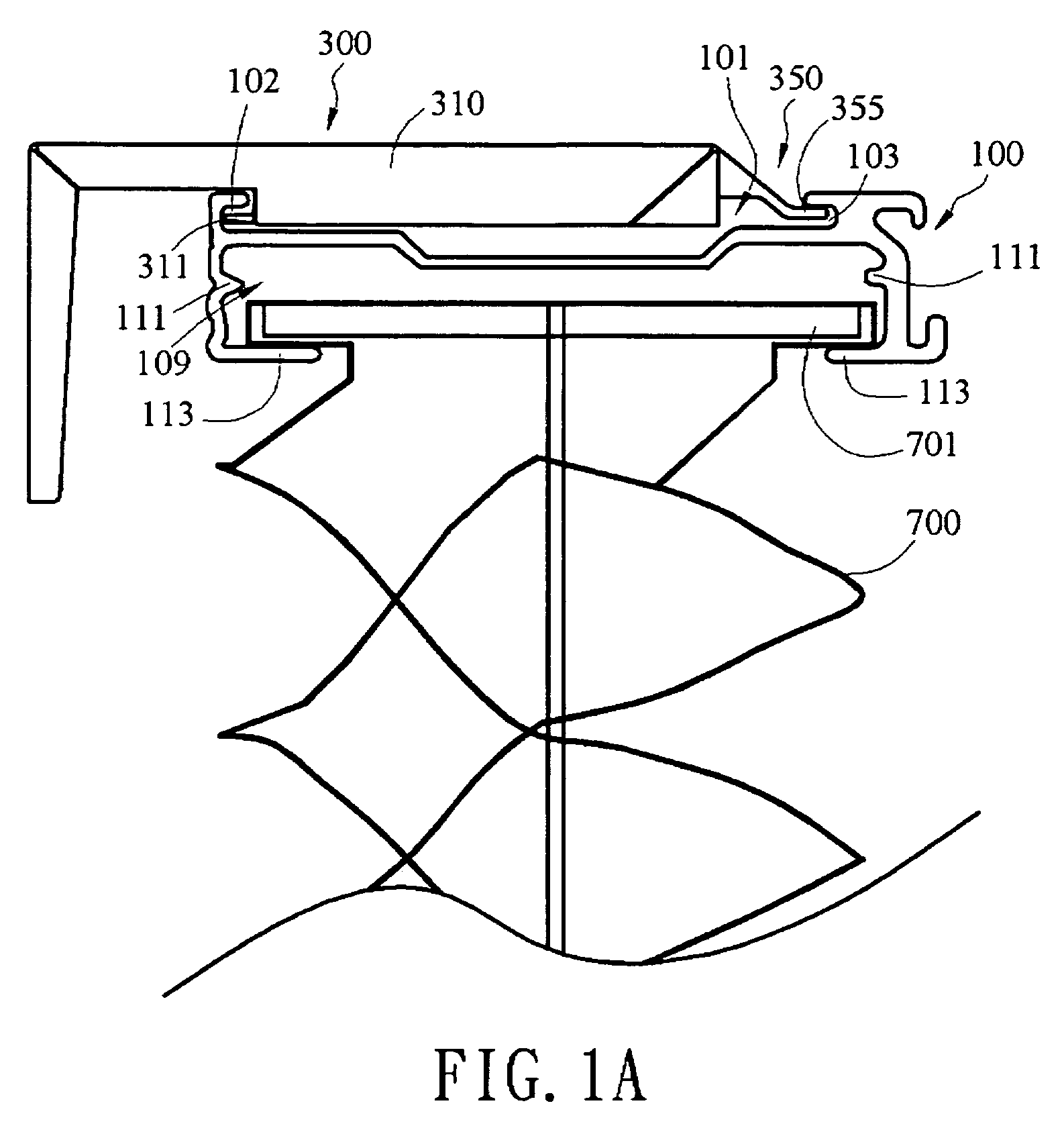
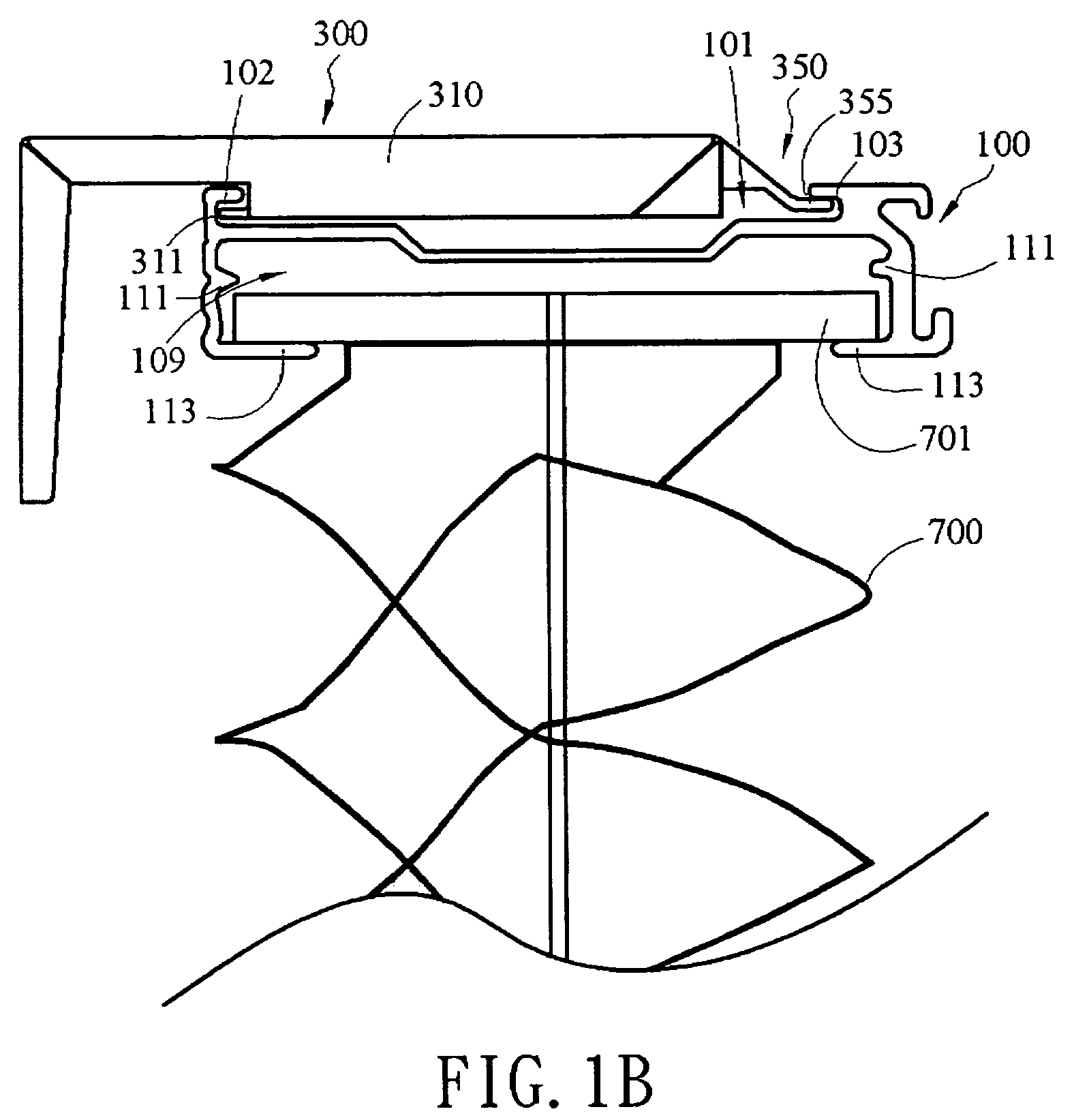
[0017]As shown in FIGS. 1A and 1B, they are schematic assembled views of the present invention. The present invention provides a bracket and head rail assembly, wherein the head rail 100 is easily gripped into or detached from the bracket 300. The bracket 300 has a claw 311 at one side and a stopper 355 at the other side, wherein the stopper 355 slides relative to the bracket 300, and thus, it can be stretched out and drawn back. A recess 101 is formed in the upper portion of the head rail 100, and two opposite ends of the recess 101 respectively extend upwardly and inwardly to form a first slot 102 and a second slot 103, wherein the first slot 102 and the second slot 103 have the same shape. During the assembling process, firstly, the second slot 103 is forced to bear against one side of the stopper 355 of the bracket 300 and slide relative to the bracket 300. When the head rail 100 is positioned, the stopper 355 is set back, such that the first slot 102 grips with the claw 311, so...


PUM


Abstract

A bracket and head rail assembly is provided. A recess is formed at both ends of the upper portion of a head rail. The recess is sunken at both sides to form a first slot and a second slot. The bracket includes a body and a fastener, wherein a claw is extended from the body, and an elastic part is extended from the fastener and bears against the body, such that the fastener is slidably disposed in the body. When being assembled, the first and second slots are easily locked with the claw and the fastener, and alternatively, they are exchanged with each other for locking with the claw and the fastener respectively. Then, the head rail and the fastener are designed into a thin configuration, and then, formed by bending and processing sheets, so as to achieve the advantages of simple assembly, mass production, and nice appearance.

Description

BACKGROUND OF THE INVENTION[0001]1. Field of Invention[0002]The present invention relates to a combination structure of a head rail and a bracket, and more particularly, to a structure with the head rail being bi-directionally locked by the bracket, which is easily assembled.[0003]2. Related Art[0004]A blind or shade can provide a protection for the privacy directed to an opened window. Therefore, the structure of the blind or shade is continuously improved. For example, U.S. Pat. No. 6,293,330 discloses a universal head rail assembly, which comprises a head rail and a universal mounting bracket. The head rail comprises a front wall and a back wall, wherein the front wall and the back wall have a first lip and a second lip formed on one end respectively. The universal mounting bracket comprises a mounting assembly and an interlocking element, wherein the mounting assembly has a notch on one side. When the head rail is to be mounted on the universal mounting bracket, the head rail be...

Claims


Application Information

Patent Timeline
Patent Type & Authority Patents(United States)
IPC IPC(8): A47H5/00
CPCE06B9/323Y10S160/902
Inventor WEN, YU-CHECHANG, CHIH-YAO
Owner NIEN MADE ENTERPRISE CO LTD
Why Eureka
Try Eureka