
Thin key sheet and thin key unit incorporating the thin key sheet

a key unit and key sheet technology, applied in the direction of contacts, contact mechanisms, legends, etc., can solve the problems of height hampering the thin configuration and limit the thinning of the key sheet, and achieve the effect of thin configuration

Inactive Publication Date: 2010-04-27
SUNARROW CO LTD
View PDF22 Cites 11 Cited by
  • Summary
  • Abstract
  • Description
  • Claims
  • Application Information

AI Technical Summary

Benefits of technology

[0013]2) A cushion gasket having appropriate elasticity was used instead of a key pad, thereby supporting a key top such that it can be displaced up and down and fixing the key top. Therefore, one of the accumulated layers (such as an adhesive layer for fixing a key top onto the key pad) is decreased, so that further thinner configuration was achieved.3) A foamed material or soft material was disposed below a key top, thereby achieving thinner configuration while enhancing a key click feel.4) In addition, it is possible to measure up to the demanders' expectation of the improvement of water proof function along with the recent penetration of handy mobile equipments such as portable phones, personal digital assistants (PDA) or the like into the daily life.

Problems solved by technology

However, as long as the prior art is followed, there is a limit for the thinning of a key sheet.
Although a light source for illuminating a key top from the back surface is small, it is a three-dimensional structure having a dimension of length, width and height like a smaller bean, and in particular its height hampers thinner configuration.

Method used


Image

  • Thin key sheet and thin key unit incorporating the thin key sheet
  • Thin key sheet and thin key unit incorporating the thin key sheet
  • Thin key sheet and thin key unit incorporating the thin key sheet

Examples


embodiment 1

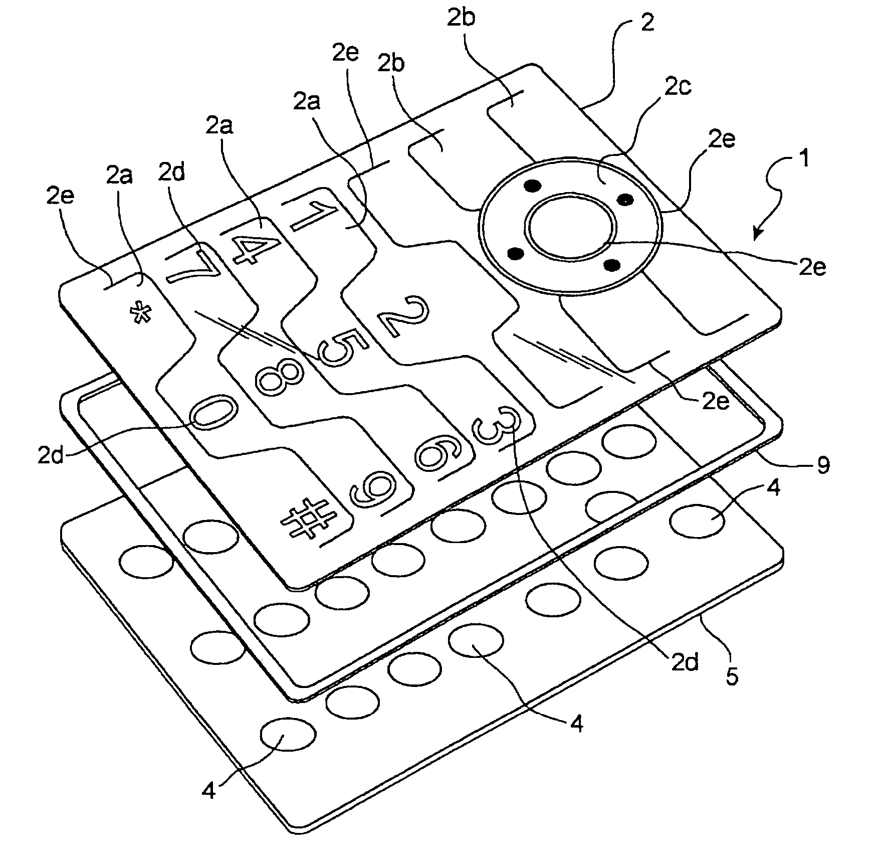
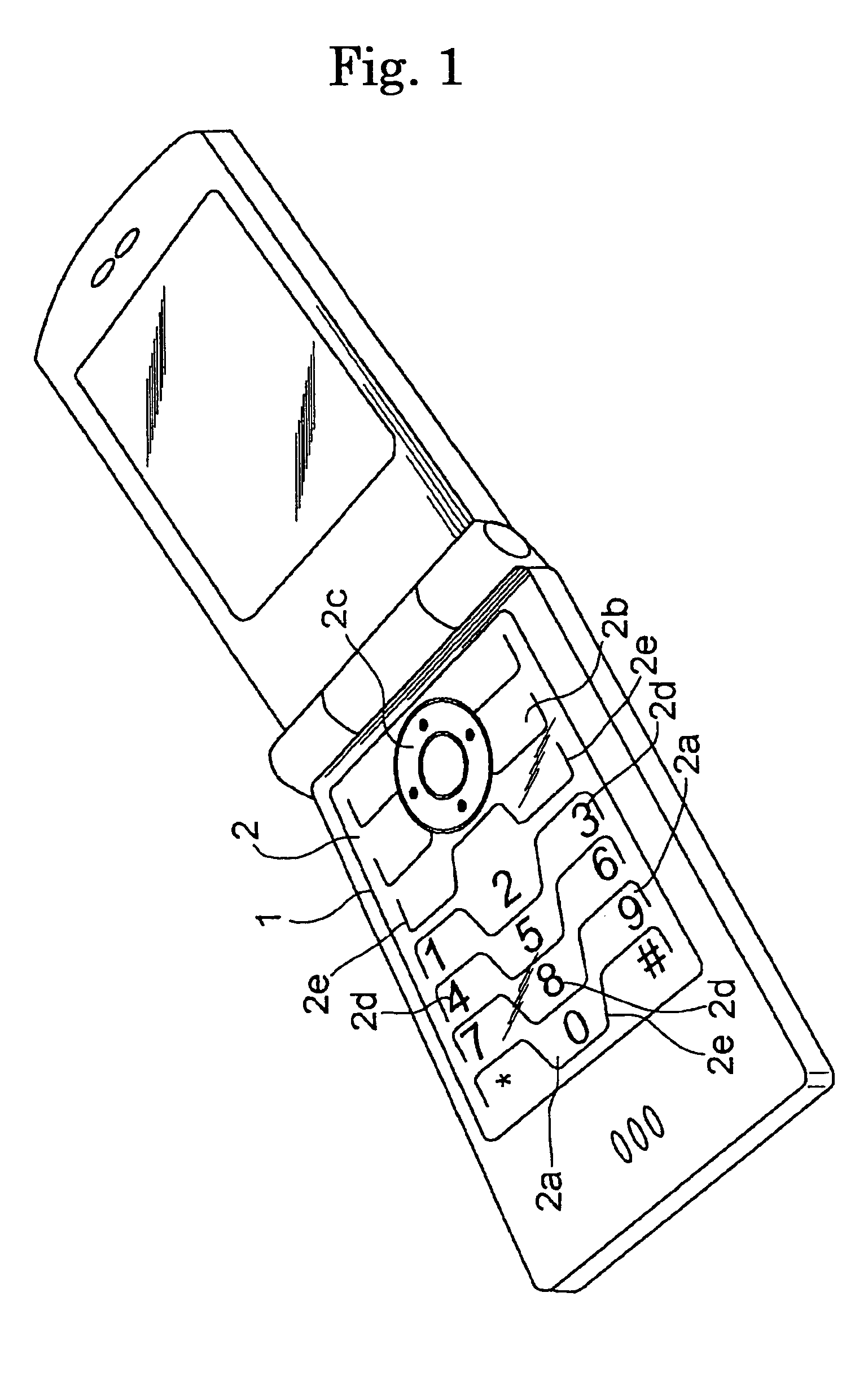
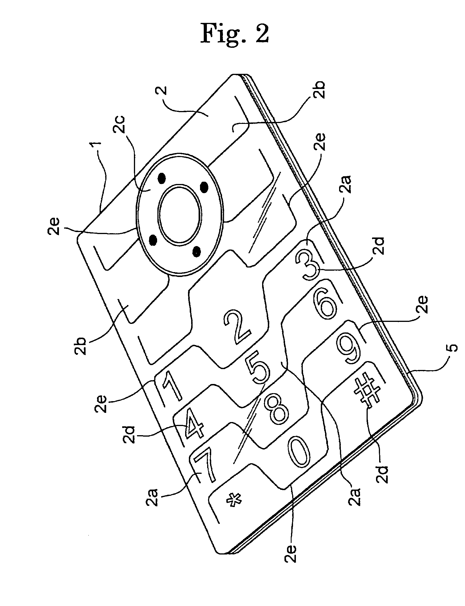
[0042]FIGS. 1 to 6 show Embodiment 1 of a thin key sheet of the present invention. As shown in FIGS. 2, 3 and 6, a key unit of the present Embodiment comprises a key sheet 1 which is configured from a key top 2 made of a thin metal plate such as stainless steel or the like and integrally formed by assembling various keys 2a, 2b and 2c, and a gasket 3 disposed along the periphery for each key. Underneath the key sheet 1, a printed circuit board 5 formed of a resin is closely disposed.

[0043]In FIG. 6, a dashed line 8 extending transversely shows a position to which, when the key top 2 is pressed, the bottom of the key top 2 is pressed down against the elasticity of the gasket 3 and metal dome 4. When the key top 2 is pressed down to the position of the dashed line 8, the metal dome 4 short-circuits between two normally open contacts (drawing omitted) disposed on the printed circuit board 5 by being pressed by a pressing element 7 on the back surface of the key top 2. Thereby, an elect...

embodiment 2

[0055]FIGS. 7 and 8 show Embodiment 2 of the thin key sheet of the present invention. As shown in FIG. 7, the thin key sheet 1A of the present Embodiment 2 comprises ten-keys 2a on which alphabets, symbols and / or numerals are respectively indicated, function keys 2b to which the functions such as power ON / OFF, the cutting of a line, e-mail or the like are allocated, and a cursor key 2c at the upper central part, and a plurality of those keys, working as a push button, are each separately formed as a plurality of key tops 2.

[0056]There is a structure in which the key tops 2 move upward and downward separately and independently corresponding to each of the keys 2a, 2b and 2c. Further, while it is not an essential configuration, a key frame 12 which is fixed onto the printed circuit board 5 with a spacer 9 being interposed so as to surround the periphery of the key top 2. Since the configuration of a key sheet 1A other than those mentioned above basically has the configuration similar ...

embodiment 3

[0057]FIG. 9 shows Embodiment 3 of the thin key sheet of the present invention. The key sheet 1B of Embodiment 3 has a structure of eliminating the scores 2e provided on the key top 2 of the key sheet 1 in the above-mentioned Embodiment 1 and corresponding to the areas of each of the keys 2a, 2b and 2c so as to separate them, and a structure of allowing the up-and-down movement which can press a metal dome only by the elasticity of the metal plate constituting the key top 2.

[0058]Consequently, the key top 2 of the key sheet 1B is set to 0.2 mm, in the same manner as the above-mentioned key top 2 of the key sheet 1, so that there does not occur the problem of deformation, being not restored to its original shape when stress is applied. Since the configuration of a key sheet 1B other than those mentioned above basically has the configuration similar to the key sheet 1, descriptions are omitted for the parts with the similar configuration by using the same symbols as those used for the...


PUM


Abstract

Mobile phones are in a trend of having thinner configuration due to emphasis on the design. Thus, in order to meet this demand, the present invention aims to thin the key sheet portion as much as possible. A thin key sheet and a thin key unit incorporating the thin key sheet are configured by providing on its surface a key top 2 made of a metal or a resin with indications such as letters, symbols, graphics or the like indicating the functions of keys are formed on the front surface or the back surface thereof, and switch elements 4 for turning ON / OFF of an electric circuit by the pressing of the key top, together with a printed circuit board 5 on which a circuit pattern involved therewith is formed; and by adhering and fixing the key top 2 and the printed circuit board 5 together via a cushion gasket 3 having appropriate elasticity and a filler layer 14 disposed between the key top and the printed circuit board.

Description

CROSS-REFERENCE TO RELATED APPLICATION[0001]The present application is a 35 U.S.C. §371 National Stage Application of, and claims priority of, International patent application Serial No. PCT / JP2005 / 024024 filed Dec. 28, 2005, now Publication No. WO 2006 / 070854, published Jul. 6, 2006, and published in Japanese, not in English, the content of which is hereby incorporated by reference in its entirety.TECHNICAL FIELD[0002]The present invention relates to a key sheet on which a plurality of keys working as input means for handy mobile equipments such as portable phones, personal digital assistants (PDA) or the like are assembled and disposed, and also relates to a technology for thinning a key unit with the key sheet being incorporated.BACKGROUND ART[0003]A key sheet is a component constituting a handy mobile equipment such as a portable phone, personal digital assistant (PDA) or the like, and a plurality of key tops working as push buttons each indicating an alphabetical and / or numeric...

Claims


Application Information

Patent Timeline
Patent Type & Authority Patents(United States)
IPC IPC(8): H01H9/00
CPCH01H13/703H04M1/23H04M1/22H01H13/88H01H2205/016H01H2209/0021H01H2209/074H01H2211/006H01H2211/026H01H2211/03H01H2215/004H01H2219/018H01H2221/006H01H2227/01H01H2227/024H01H2227/036H01H2229/028H01H2229/058H01H2231/022
Inventor KENMOCHI, YOSHIO
Owner SUNARROW CO LTD
Learn More