Tool having integrated electricity generator with external stator

a technology of electricity generator and stator, which is applied in the direction of electric generator control, portable power-driven tools, machines/engines, etc., can solve the problems of labor-intensive procedures and the inability to achieve the effect of reducing the overall circuit resistance, improving the operational electrical efficiency of power distribution, and simplifying the construction of the pneumatic tool itsel

Active Publication Date: 2010-04-27
1543803 ONTARIO LTD +1
View PDF31 Cites 45 Cited by
  • Summary
  • Abstract
  • Description
  • Claims
  • Application Information

AI Technical Summary

Benefits of technology

[0071]The integrated electricity generator disclosed herein provides several advantages. In particular, it is not required to pass lead wires through feed-through conduits in order to generate electricity for use outside of the tool housing from the relative movement of the rotor and the stator. Furthermore, hermetic sealing previously required for feed-through conduits is not required. It will be understood that obviating the lead wires also obviates the related manufacturing steps necessary for their placement. Overall circuit resistance is also reduced, improving the operational electrical efficiency of power distribution to storage components, integrated circuits and LEDs. Because the tool cover is configured to support and align the inductor element and circuitry of the stator with respect to the rotor, construction of the pneumatic tool itself is further simplified. Yet another advantage is that the stator does not depend, rely on, or affect any of the engineered mechanical tolerances of existing air tool designs. Conversely speaking, the stator component dimensions are not governed by critical tolerances of the mechanical parts designed to drive a pressurized fluid driven tool efficiently. As compared to prior art methods directly involving modifications to motor parts and in particular, an end plate supporting a rotor, this approach does not constrict stator size (or output) to minimal air-motor volumes or to limits restricted by the size of internal motor elements. The degrees of freedom to designing an appropriate sized stator to fulfill a specific electronic objective are therefore increased, allowing design to a higher degree to be informed by the external boundary of the tool or what may otherwise be deemed commercially acceptable tool aesthetics.

Problems solved by technology

Additionally, during tool assembly and service a labor-intensive procedure is needed to resolve the physical placement of lead wires through a motor bore, tool housing and feed-through conduit from an internal stator.
Furthermore, it is an electronic challenge to provide a secure, vibration damped environment for mounting printed circuit boards containing sensitive integrated circuit (IC) components and sensors, whether on a metallic bodied tool surface or in a cavity thereon, while also providing a nonconductive and static-free and dry environment.
Experience in the art teaches that pneumatic motor resonations can produce deleterious effects on some electronic components hard-mounted onto the tool housing.

Method used


Image

  • Tool having integrated electricity generator with external stator
  • Tool having integrated electricity generator with external stator
  • Tool having integrated electricity generator with external stator

Examples


Embodiment Construction

[0092]For the purpose of this specification, it will be clearly understood that the word “comprises” means “including but not limited to” and that the word “comprising” has an equivalent meaning.

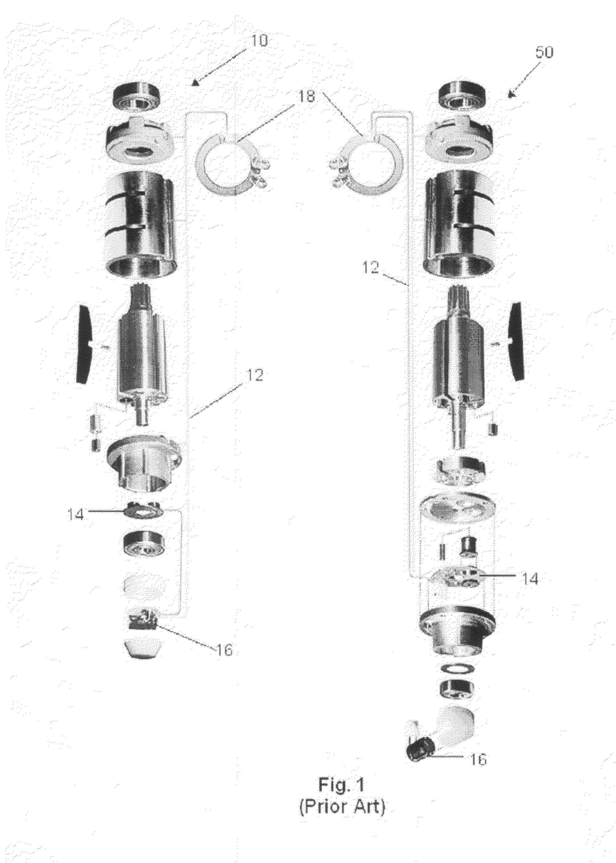
[0093]FIG. 1 shows exploded views of two prior art air-motor integrated electric generators and supporting components generally at 10 and 50. It can be seen that physical wires 12 are required to carry electrical current from the stator including the inductor 14 and supporting circuitry 16 that is positioned within the pressurized tool housing (not shown in FIG. 1) through to the low pressure exterior of the tool housing. The electrical current supplies respective light ring luminaire 18 for use outside of the tool housing to light the immediate surface area of a workpiece. The supporting circuitry of the stator is potted (epoxy encapsulated) to prevent interference of moisture and high-pressure air with its sensitive electrical components. Not shown in FIG. 1 but required in such prior art ...


PUM


Abstract

A tool includes a nonmagnetic tool housing; a cylindrical rotor inside the tool housing and rotatable in response to a flow of pressurized fluid through the tool housing; magnets mounted in the rotor; and a stator on the exterior of the tool housing. The stator is dimensioned to cooperate with the magnets to, upon rotation of the rotor, generate electrical current for supply to a load.

Description

REFERENCE TO RELATED APPLICATION[0001]This application claims priority under 35 U.S.C. 119(e) from U.S. Provisional Patent Application No. 60 / 855,124 filed Oct. 30, 2006.FIELD OF THE INVENTION[0002]The following relates generally to pneumatic tools with integrated electricity generators and more particularly to an integrated electricity generator for a pneumatic tool with a stator that is positioned on the outside of the pneumatic tool housing.BACKGROUND OF THE INVENTION[0003]Conventional pneumatic tools, such as a pneumatic wrench, sander or grinder typically include a fluid driven motor comprised of a rotor having sliding vanes and mounted for rotation on ball bearings enclosed within a pressure-tight tool housing. The ball bearings are supported by front and rear end plates positioned on each end of a motor cylinder having an offset annular bore, relative to its external diameter and running parallel to the cylinder length. The rotor runs longitudinally through offset annular bor...

Claims


Application Information

Patent Timeline
Patent Type & Authority Patents(United States)
IPC IPC(8): F03B13/00
CPCH02K7/1823H02K1/278B25F5/021
Inventor LEININGER, JON J.
Owner 1543803 ONTARIO LTD
Why Eureka
Try Eureka