Light control circuit

a control circuit and light control technology, applied in the direction of electric variable regulation, process and machine control, instruments, etc., can solve the problems of increasing circuit size, flickering near the threshold of a/d converter b>24/b>, and eye discomfort, so as to achieve excellent effects and smooth light control.

Inactive Publication Date: 2010-04-27
ALPS ALPINE CO LTD
View PDF4 Cites 16 Cited by
  • Summary
  • Abstract
  • Description
  • Claims
  • Application Information

AI Technical Summary

Benefits of technology

[0014]In the light control circuit described above, the illuminance sensor outputs a current which increases or decreases in an analog manner corresponding to the increasing or decreasing change of the illuminance of surrounding light, and the light-emitting device driver of the driving control circuit outputs to the light-emitting device the voltage for holding a voltage, which is obtained when the current flowing through the light-emitting device and the current detected by the illuminance sensor flows through the detection resistor, in the predetermined value all the time. Accordingly, it is possible to control the amount of light emitted from the light-emitting device in correspondence with the change of surrounding illuminance in an analog manner. In addition, the light-emitting device can emit a large amount of light in a dark place and emit a small amount of light in a bright place. As described above, according to the aspect of the invention, a light control can be made very smoothly. As a result, it becomes very easy to realize a light control in a desired dynamic range without flickering at the time of light emission and a stepwise change of the brightness.
[0015]As described above, according to the light control circuit, it is possible to appropriately control the amount of light emitted from the light-emitting device in correspondence with the change of the surrounding illuminance in an analog manner. More specifically, it is possible to achieve excellent effects described above.

Problems solved by technology

However, this know device has the following problems.
As a result, the eyes feel very uncomfortable.
Further, this device also has a disadvantage in that flickering occurs near the threshold of the A / D converter 24, for example, in an ‘a’ portion of FIG. 6 due to the change of the brightness of the lighting device.
In this case, however, the size of a circuit increases.
As a result, the cost increases.
Furthermore, in the case when a period of a PWM output to the lighting device is long, flickering has occurred.
As a result, there has been a problem in that the power consumption of a control circuit increases due to the high-speed clock.
In addition, in the case when the PWM period is made short, it has been difficult to minutely control the duty.
As a result, there has been a problem in that the circuit size increases.
In the related art, there has been no light control device capable of properly controlling the amount of emitted light in an analog manner in correspondence with the both cases described above.
In addition, the light-emitting device can emit a large amount of light in a dark place and emit a small amount of light in a bright place.

Method used


Image

  • Light control circuit
  • Light control circuit
  • Light control circuit

Examples


Embodiment Construction

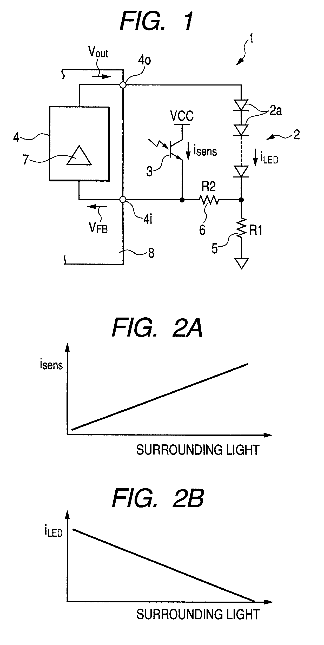
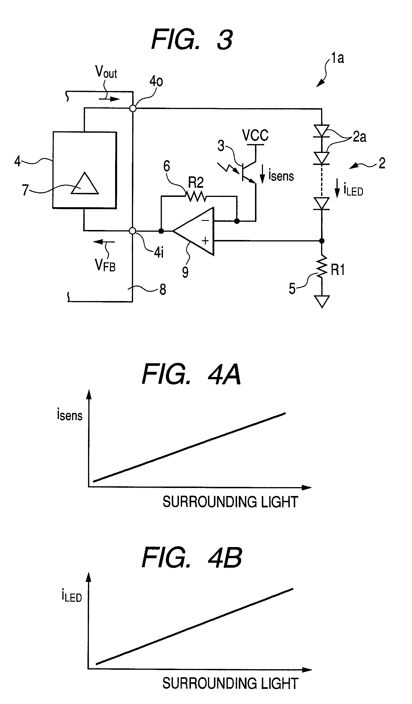
[0024]Hereinafter, a light control circuit according to an embodiment of the invention will be described with reference to FIGS. 1 to 4B.

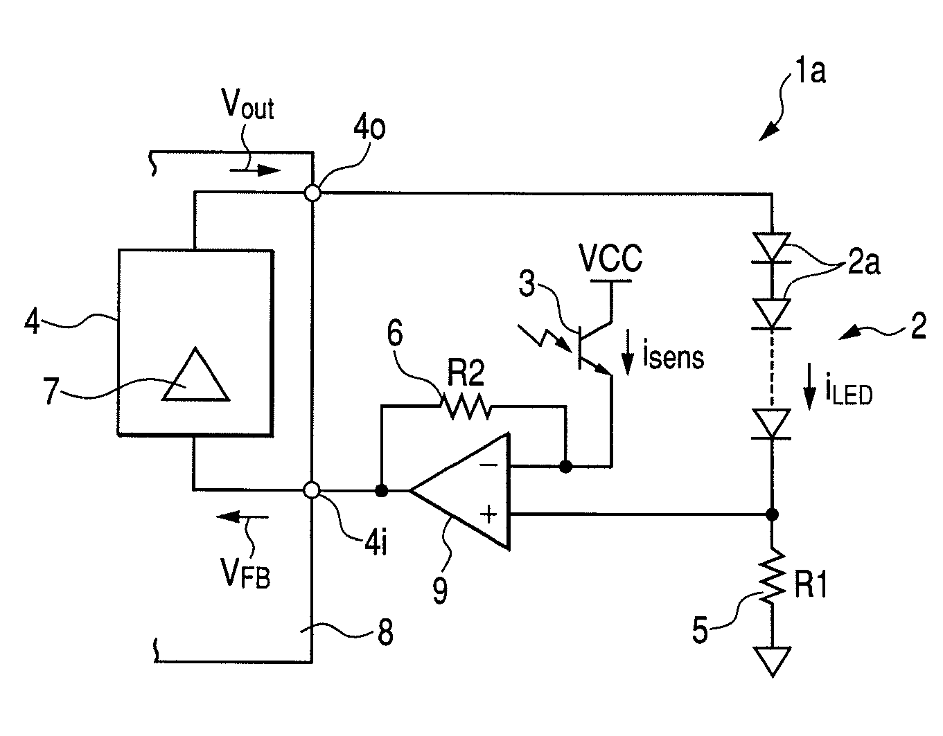
[0025]FIG. 1 illustrates the configuration of a circuit according to an embodiment of the invention. A light control circuit according to the present embodiment is a circuit suitable for light control of a lighting device of a liquid crystal device having a reflective LCD or a transflective LCD in which reflection weighs.

[0026]A light control circuit 1 according to the present embodiment includes: a light-emitting device 2 in which a plurality of LEDs 2a serving as a luminous body of a lighting device (not shown) are connected in series; an illuminance sensor 3 that detects the illuminance of surrounding light of the lighting device; and a driving control circuit 4 that controls the amount of emitted light of the light-emitting device 2 corresponding to the illuminance detected by the illuminance sensor 3 so as to cause the light-emitting device 2 ...


PUM


Abstract

An illuminance sensor is formed as a current output type sensor that outputs a current which increases or decreases in an analog manner corresponding to an increasing or decreasing change of the illuminance. A light-emitting device is connected with a detection resistor that detects a current flowing through a light-emitting device. A driving control circuit has a light-emitting device driver that outputs to the light-emitting device a voltage for holding a voltage, which is obtained when a current flowing through the light-emitting device and a current detected by the illuminance sensor flows through the detection resistor, in a predetermined value all the time. The light-emitting device emits a large amount of light in a dark place and emits a small amount of light in a bright place.

Description

CLAIM OF PRIORITY[0001]This application claims benefit of the Japanese Patent Application No. 2006-252545 filed on Sep. 19, 2006, which is hereby incorporated by reference.BACKGROUND[0002]1. Field of the Invention[0003]The present invention relates to a light control circuit, and in particular, to a light control circuit suitable for a brightness control of a lighting device that illuminates a liquid crystal device.[0004]2. Description of the Related Art[0005]In general, in a liquid crystal device used as an image display unit of a mobile phone or the like, a lighting device that illuminates a liquid crystal device is provided and the brightness of a screen is controlled corresponding to the surrounding brightness.[0006]Various kinds of light control devices for the brightness control have been proposed (for example, see JP-A-10-191467 and JP-A-2003-68480).[0007]A known light control device disclosed in JP-A-10-191467 is formed as shown in FIG. 5, for example. Referring to FIG. 5, a...

Claims


Application Information

Patent Timeline
Patent Type & Authority Patents(United States)
IPC IPC(8): H05B37/02
CPCH05B33/0851H05B45/12H05B47/11Y02B20/40
Inventor WATANABE, MINORUKANO, MITSURUFUJIWARA, MINORU
Owner ALPS ALPINE CO LTD
Why Eureka
Try Eureka