In situ rechargeable battery and charging stand

a rechargeable battery and charging stand technology, applied in the direction of secondary cell servicing/maintenance, cell components, sustainable manufacturing/processing, etc., can solve the problems of battery dropping, battery falling out of the appliance, affecting the service life of the battery, etc., to save battery energy, improve convenience and cost, and significant cost and reliability benefits

Inactive Publication Date: 2010-04-27
DENOVO RES
View PDF17 Cites 41 Cited by
  • Summary
  • Abstract
  • Description
  • Claims
  • Application Information

AI Technical Summary

Benefits of technology

[0011]The present invention includes a small secondary button cell battery having a chemistry that is appropriate to the intended use, a case configuration that tends to resiliently compress the battery chemistry at all times during the discharge-recharge cycle, a flexibly configured separator, and a self contained recharging circuit. The structural elements of the button cell (case and separator) are all recoverably deformable to accommodate the volumetric changes that inherently occur during the discharge-recharge cycle of an electrochemical cell without suffering permanent deflection or distortion. In one preferred embodiment the recharging circuit can be, for example, one or more energy harvesting diodes. Charge control is provided by directly or indirectly detecting the level of charge on the battery and controlling the amount of applied charging energy in response to the detected charge level. A recharging station is also provided according to the present invention. The recharging station is adapted to recharging the battery while it is in operative association with an electronic appliance without electrically conductive contact between the recharging station and either the battery or the appliance in which it is mounted. Having all of the recharging circuitry in the battery itself provides significant cost, reliability, and convenience benefits. Once installed, a rechargeable battery according to the present invention, particularly a button battery, generally need not be removed from the associated appliance for the life of the rechargeable battery. Because the battery can be recharged numerous times, the battery need not be removed or handled for extended periods of time, for example, in a conventional hearing aid appliance. This is a significant improvement in convenience and cost over the present widely used non-rechargeable button battery that must be replaced about once a week. Additional convenience and safety are afforded by the present invention as against the use of previous expedients. For instance, in previous expedients the battery door of an appliance, for example, a hearing aid appliance, had to be opened when the hearing aid was not being worn. This was done to turn off the hearing aid. This conserved battery energy and silenced the acoustic feedback “squeal” that is typically emitted from a hearing aid when it is not being worn. Unfortunately, when the battery door was opened, the battery had a tendency to fall out of the appliance. Because of its small size and round wheel like shape, when the battery fell out it tended to roll. In many instances, the dropped battery was lost.
[0012]According to the present invention, these and other difficulties of previously proposed expedients are eliminated. According to the present invention the recharging station can be configured to automatically turn off the electronic appliance every time it is placed on the recharging station, or to utilize the “on” stage of the appliance as part of the charge control during the recharging phase of the discharge-recharge cycle. Generally, it is preferred to employ a recharging station that is conductively connected to the conventional house current that is generally available in the area. Portable battery powered recharging stations, however, have some utility. If the user wishes to turn off the appliance when a regular recharging station is not readily at hand, the appliance can be placed temporarily in a portable battery operated pocket sized recharger. By so doing, the appliance can be, for example, turned off and the battery can be “topped off” thus giving it an even longer period of use before it requires an extended recharging.
[0013]The long battery life cycle according to the present invention permits the provision of yet another option to a user who wishes to turn off the electronic appliance. A user can turn off the appliance by opening the battery door without risk that the battery will fall out of the appliance if an adhesive is employed to mount the battery in the battery compartment of the appliance. It is possible to adhesively secure the button battery in operative configuration with the appliance because the battery does not have to be replaced but approximately once a year.

Problems solved by technology

Having all of the recharging circuitry in the battery itself provides significant cost, reliability, and convenience benefits.
Unfortunately, when the battery door was opened, the battery had a tendency to fall out of the appliance.
Because of its small size and round wheel like shape, when the battery fell out it tended to roll.
In many instances, the dropped battery was lost.

Method used


Image

  • In situ rechargeable battery and charging stand
  • In situ rechargeable battery and charging stand
  • In situ rechargeable battery and charging stand

Examples


Embodiment Construction

[0026]Referring now to the drawings wherein like reference numerals designate identical or corresponding parts throughout the several views. It is to be understood that the drawings are diagrammatic and schematic representations of various embodiments of the invention, and are not to be construed as limiting the invention in any way. The use of words and phrases herein with reference to specific embodiments is not intended to limit the meanings of such words and phrases to those specific embodiments. Words and phrases herein are intended to have their ordinary meanings, unless a specific definition is set forth at length herein.

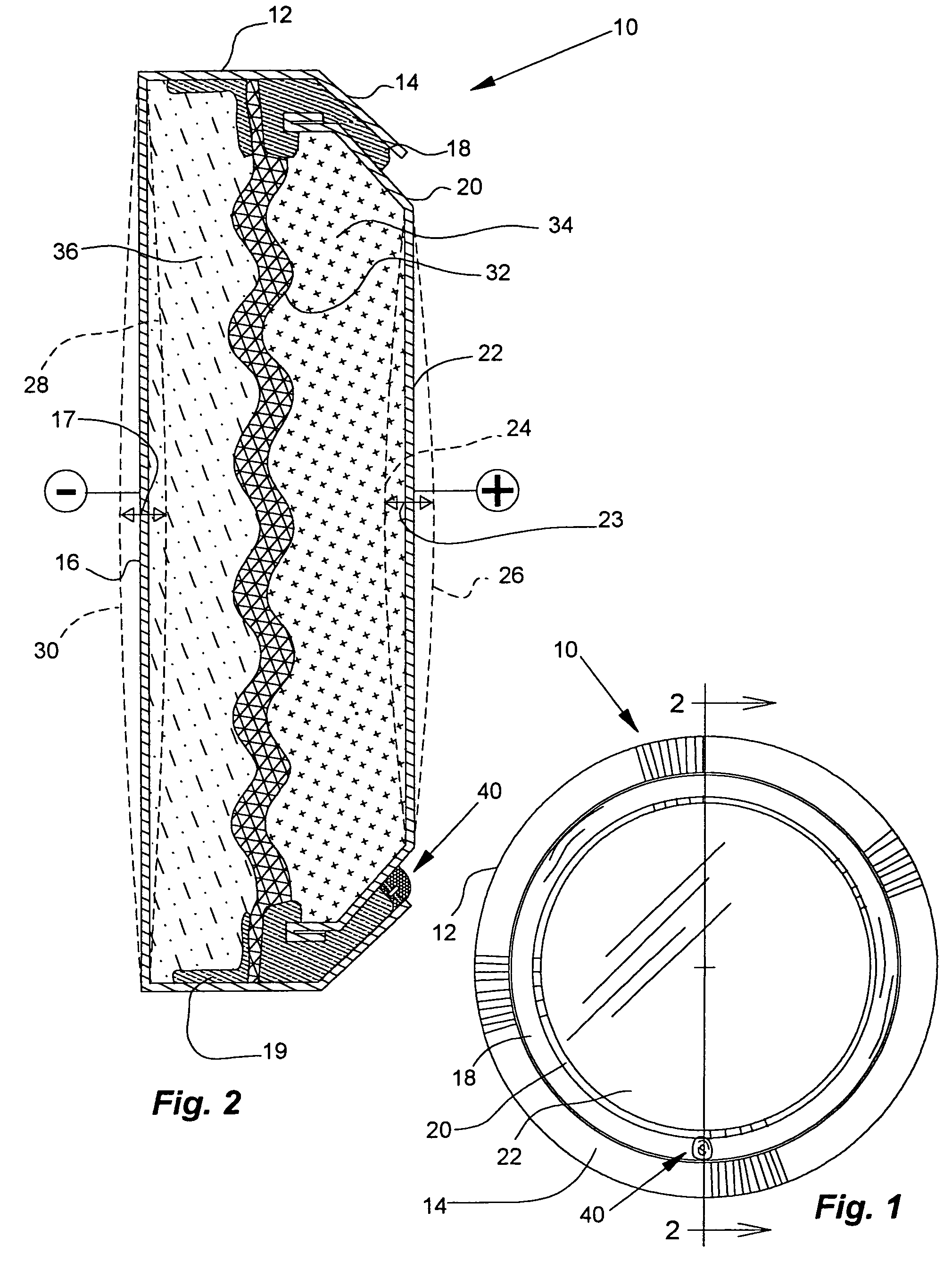
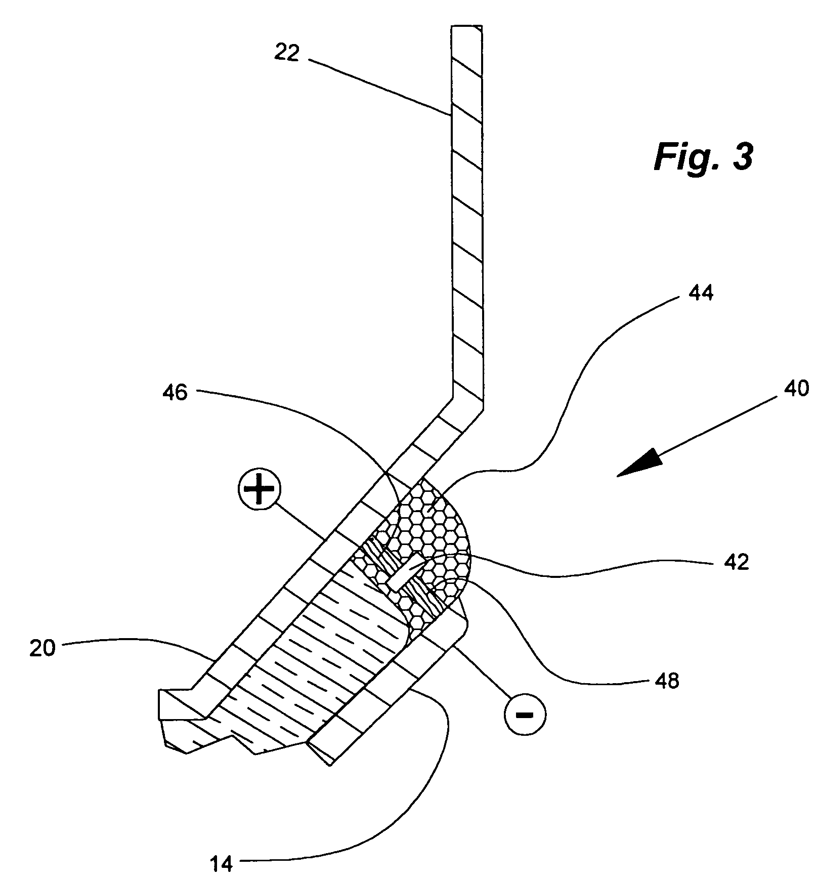
[0027]Referring particularly to the drawings, there is illustrated generally at 10 a secondary battery having a button cell form wherein the chemistry is resiliently compressively enclosed within a resiliently deformable case and separated by a flexibly configured separator. Certain features are illustrated out of proportion for the purposes of illustration.

[...


PUM

PropertyMeasurementUnit
frequencyaaaaaaaaaa
energyaaaaaaaaaa
radio frequency energyaaaaaaaaaa

Abstract

A secondary button cell battery that is particularly suited for use in hearing aid appliances, and an associated charging station. Recharging is accomplished without direct conductive connection between the source of the energy and either the battery or its appliance. Radio frequency energy is harvested in an enclosed chamber in a charging station and applied to the recharging of the button cell. Such energy is harvested by the use of one or more energy harvesting diodes connected in parallel with the battery. Multiple diodes connected in parallel or serial may be used to adjust charging current or voltage or both. Charge control is provided by directly or indirectly detecting the level of charge on the cell. Where the associated appliance is a hearing aid, the charge level detection may be accomplished acoustically by determining the characteristics of the sound emitted by the hearing aid, and charging is accomplished with the cell within the hearing aid appliance.

Description

RELATED APPLICATIONS[0001]This application claims the benefit of U.S. Provisional Application Ser. No. 60 / 516,205, filed Oct. 31, 2003.BACKGROUND OF THE INVENTION[0002]1. Field of the Invention[0003]The invention relates in general to methods and devices for small secondary batteries and the recharging thereof, and in particular, rechargeable hearing aid batteries and recharging appliances therefor.[0004]2. Description of the Prior Art[0005]As is well known in the fields where small batteries are used to power electronic devices, and in particular in the hearing aid field, secondary batteries require periodic recharging and primary batteries require frequent replacement. Previous primary batteries typically lasted no more than, for example, approximately one week in hearing aid appliances. Such replacement of primary batteries requires physical manipulation of the small batteries. However, those hearing-impaired persons needing an aid are often afflicted with arthritis or other ailm...

Claims


Application Information

Patent Timeline
Patent Type & Authority Patents(United States)
IPC IPC(8): H02J7/00H01M10/04H01M10/42H01M10/44H01M10/46H01M50/469H02J7/02
CPCH01M10/0427H01M10/4242H01M10/425H02J7/025H01M10/4264H01M10/44H01M10/46H01M10/4257H01M2/18H02J50/001H02J7/0042Y02E60/10Y02P70/50H01M50/469H02J50/20
Inventor SILVERMAN, MARTIN S.
Owner DENOVO RES
Why Eureka
Try Eureka