Over-voltage indicator and related circuit and method

a technology of over-voltage indicator and circuit, applied in the direction of electronic switching, emergency protective arrangements for limiting excess voltage/current, pulse technique, etc., can solve the problem of abnormal voltage level at the i/o port, affecting the reliability of the transistor mbb>2/b>, so as to avoid over-voltage damage

Inactive Publication Date: 2010-04-27
FARADAY TECH CORP
View PDF4 Cites 4 Cited by
  • Summary
  • Abstract
  • Description
  • Claims
  • Application Information

AI Technical Summary

Benefits of technology

[0011]An objective of the invention is providing an over-voltage indicator, related circuit / system and method. According to the disclosure of the invention, an over-voltage indicator is set in an I / O circuit of a system circuit (e.g., a chip or an IC) for providing an indication signal (which can be a logic signal) according to occurrence of over-voltage. The indication signal is fed-back to an internal circuit (a pre-driver or a core circuit) of the system circuit, such that the internal circuit can perform a protection procedure in response of over-voltage. For example, signal level outputted to the I / O circuit can be kept in a safe level, so as to avoid over-voltage damage in a transmission gate of a gate tracking circuit in the I / O circuit.
[0016]With circuit structures mentioned above, another objective of the invention is providing a method for over-voltage indication, which switches between two states. The method includes: in a detection state, comparing whether a signal level at the I / O port is higher than a voltage (VCCA+Vtp); if so, asserting a logic high level in the indication signal, and terminating the detection state for switching to a timing state; otherwise keeping a logic low level in the indication signal and maintaining in the detection state. In the timing state, timing for a predetermined interval and terminating the timing state for switching to the detection state. Switching between the states not only detects beginning and end of over-voltage, also protects the over-voltage indicator from being damaged by long exposure in over-voltage.
[0017]Still another objective of the invention is providing a method capable of handling over-voltage events at an I / O port of a system circuit (a chip or an IC), the method includes: performing an over-voltage indication for providing an indication signal to indicate whether over-voltage occurs at the I / O port; feeding-back the indication signal to the internal circuit; and when the indication signal indicates over-voltage, making the internal circuit perform a protection procedure in response of over-voltage. As the example discussed above, the internal circuit can keep a high level input for the gate-tracking circuit to resolve gate oxide reliability issue during over-voltage.

Problems solved by technology

That is, because of unexpected short-circuit or other reasons, voltage level at the I / O port may rise abnormally, even rise above the operation bias voltage of the I / O circuit 12.
However, the prior art I / O circuit 10 in FIG. 1 has some disadvantages while performing over-voltage protection.
For example, when over-voltage happens, reliability of the transistor Mb2 can be damaged.
This over-voltage voltage difference usually can reach a level close to breakdown voltage of the gate oxide of the transistor Mb2, and thus make the transistor Mb2 vulnerable.
The aforementioned reliability concern also addresses anther disadvantage of the prior art: the prior art over-voltage protection technique can not inform the internal circuit 12 of incoming over-voltage, leaving no room for the internal circuit 12 to properly response the over-voltage events.

Method used


Image

  • Over-voltage indicator and related circuit and method
  • Over-voltage indicator and related circuit and method
  • Over-voltage indicator and related circuit and method

Examples


Embodiment Construction

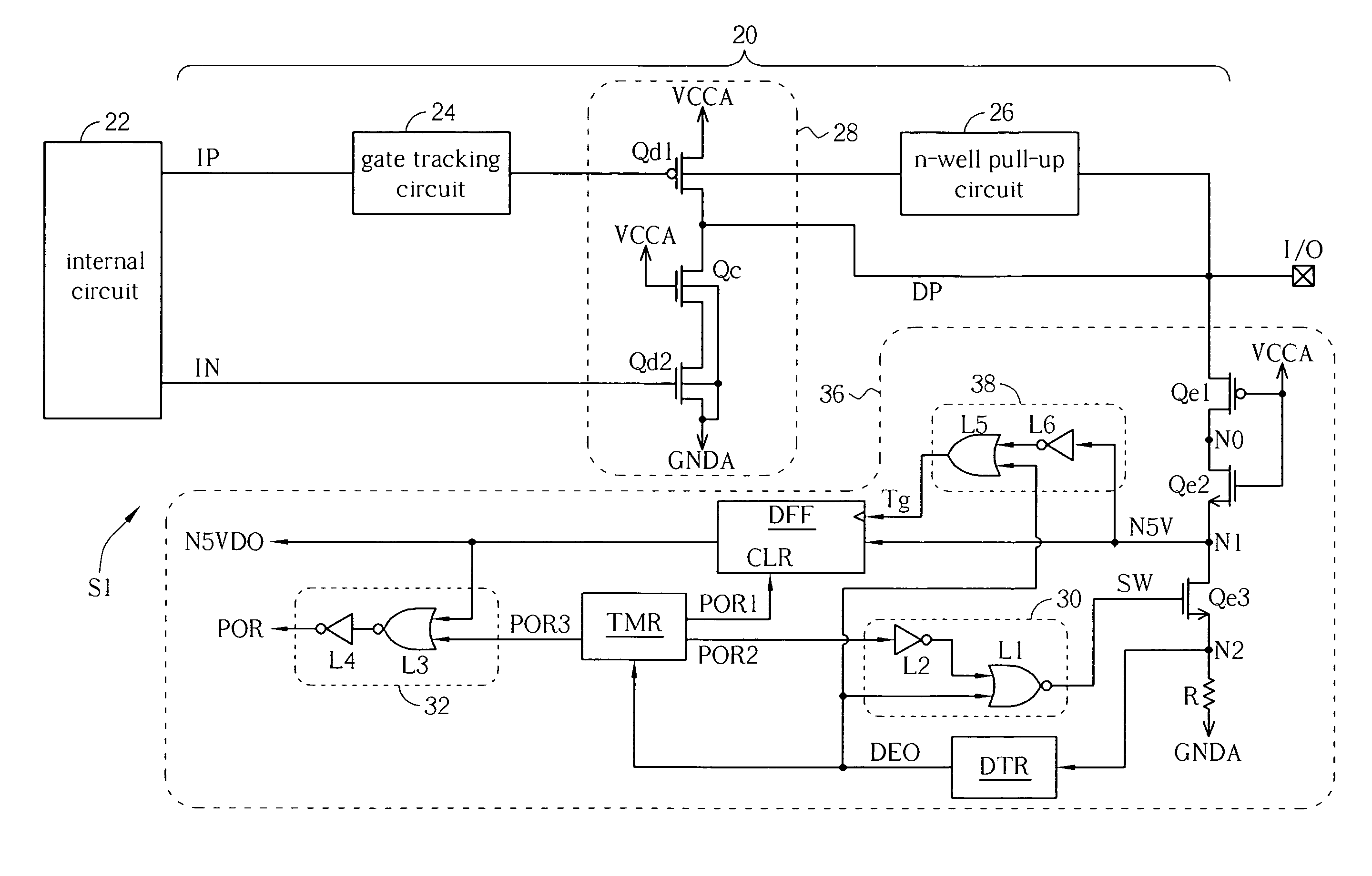
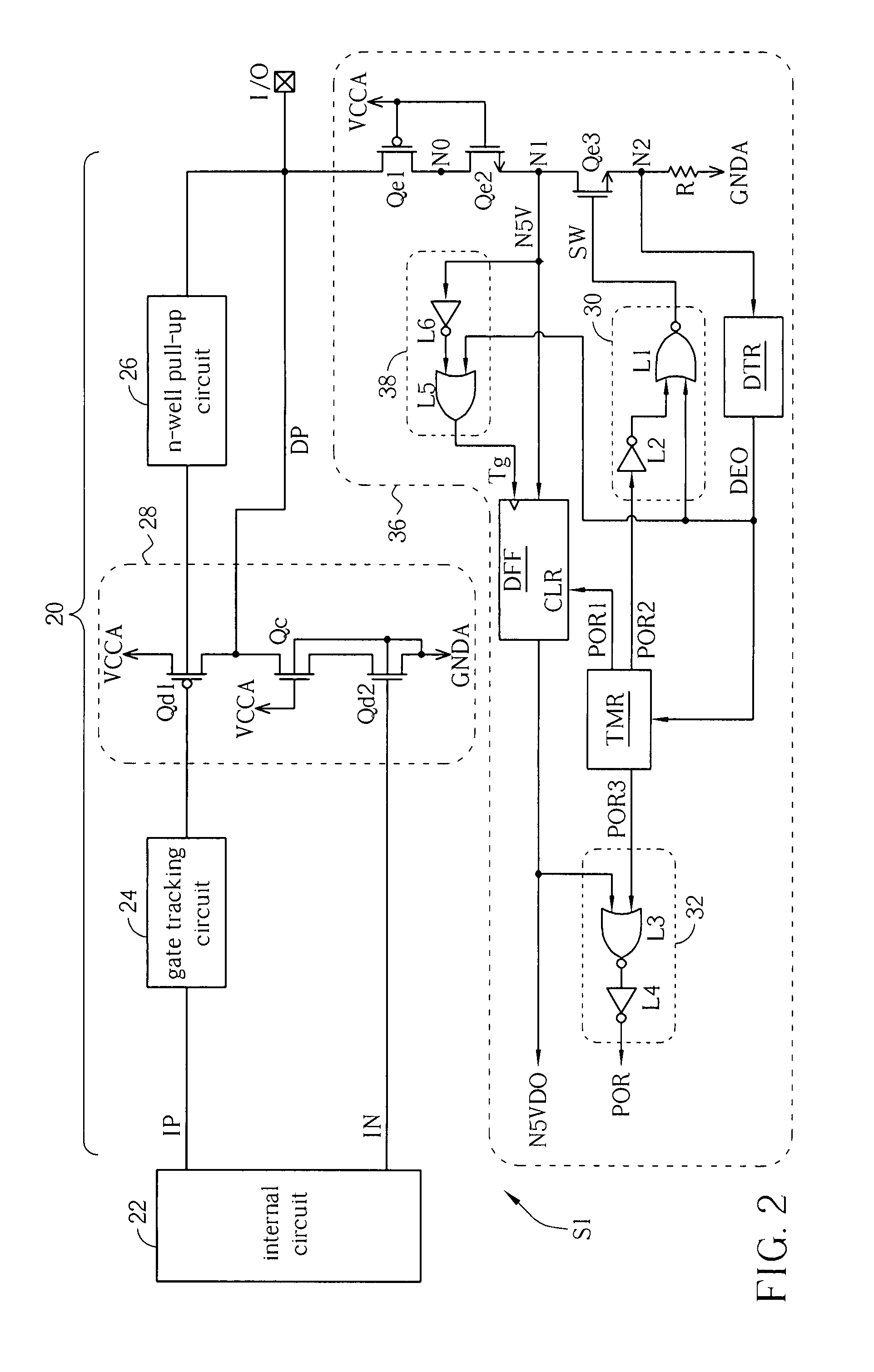
[0024]Please refer to FIG. 2; FIG. 2 illustrates an exemplary embodiment of an over-voltage indicator 36 set in a system circuit S1 (e.g., an IC or a chip) according to the presented invention. As shown in FIG. 2, the system circuit S1 may have an internal circuit 22 and an I / O circuit 20. The internal circuit 22 may be a core circuit of the system circuit S1 or a pre-driver for signal outputting. The I / O circuit 20 includes a buffer 28 for signal driving. The buffer 28 is connected between the internal circuit 22 and an I / O port (labeled as I / O in FIG. 2), wherein the I / O port may be an I / O pad (or pin) of the system circuit S1. Information outputted from the internal circuit 22 can be inputted to the I / O circuit 20 by input signals IP and IN (the signals IP and IN may be a differential pair of signals). Then the buffer 28 in the I / O circuit 20 can drive an output signal DP at the I / O port according to the input signals IP and IN, such that information of the internal circuit 22 ca...


PUM


Abstract

Over-voltage indicator and related circuit and method. The over-voltage indicator can work with an I / O circuit of a chip for detecting over-voltage in an I / O pad and providing an indication signal accordingly. When over-voltage does not happen, the over-voltage indicator continues to detect a signal level of the I / O pad and keeps the indication signal low. Once over-voltage is detected, the over-voltage indicator pauses detecting, asserts a high level in the indication signal, and periodically resumes detecting until end of over-voltage is detected. With informing provided by the indication signal, a core cell of the chip can perform proper operation to reduce potential damage caused by over-voltage.

Description

FIELD OF THE INVENTION[0001]An over-voltage indicator and related circuits and methods are provided, more specifically, an over voltage indicator, related circuits and methods where periodic detecting and pausing detecting are alternatively switched during over-voltage and a logical indication signal can be provide to activate proper protection procedure are provided.BACKGROUND OF THE INVENTION[0002]System circuits like chips, integrated circuits (ICs) and system-on-chip (SOC) have become the key hardware components in modern information society. Generally speaking, a chip has a core circuit and an I / O circuit. The core circuit implements main functions of the chip, e.g., logic operations, signal processing / conversion, coding / decoding and data management. The I / O circuit handles input / output signal exchange with external circuits through pins and pads of the chip, such that the core circuit can communicate with external circuits. Because the I / O circuit directly interfaces external ...

Claims


Application Information

Patent Timeline
Patent Type & Authority Patents(United States)
IPC IPC(8): H02H3/027
CPCH03K17/08H03K17/18H03K19/00315H03K17/223H03K2217/96054H03K2217/0018
Inventor HSIUNG, WEN-CHINGCHANG, JENG-DAULAI, CHIA-LIANGCHEN, KUAN-YU
Owner FARADAY TECH CORP
Why Eureka
Try Eureka