Pick and place machine with workpiece motion inspection

a technology of workpiece motion and pick and place machine, which is applied in the direction of instruments, computing, electrical equipment, etc., can solve the problems of programming time and maintenance efforts, and consuming plant floor space, so as to achieve the effect of optimizing the operation of the pick and place machin

Inactive Publication Date: 2010-04-27
CYBEROPTICS
View PDF214 Cites 19 Cited by
  • Summary
  • Abstract
  • Description
  • Claims
  • Application Information

AI Technical Summary

Benefits of technology

[0011]Embodiments of the present invention improve upon component level inspection performed by pick and place machines. Such improvements include detecting and measuring the motion or vibration of the workpiece during the placement cycle to determine the rigidity of the workpiece and proper placement of workpiece supports and the distance the nozzle travels during the placement cycle. Using embodiments of the present invention, the operation of the pick and place machine can be optimized or at least improved through analysis of workpiece vibration, proper design and placement of the board support mechanisms including the elimination of needed pins, the length and status of the placement nozzles, and verification of using the correct vertical travel for the nozzles.

Problems solved by technology

Pick and place machine operation is challenging.
While such systems provide highly useful inspection, they do consume plant floor-space as well as programming time and maintenance efforts.
While the disclosure of Asai et al. marks one attempt to employ in-machine component level inspection, there remains much work to be done.
While this approach is useful for determining the absence or presence of a component after placement, there are several important machine characteristics of the placement machine that can cause placement errors of components that this approach does not address.

Method used


Image

  • Pick and place machine with workpiece motion inspection
  • Pick and place machine with workpiece motion inspection
  • Pick and place machine with workpiece motion inspection

Examples


Embodiment Construction

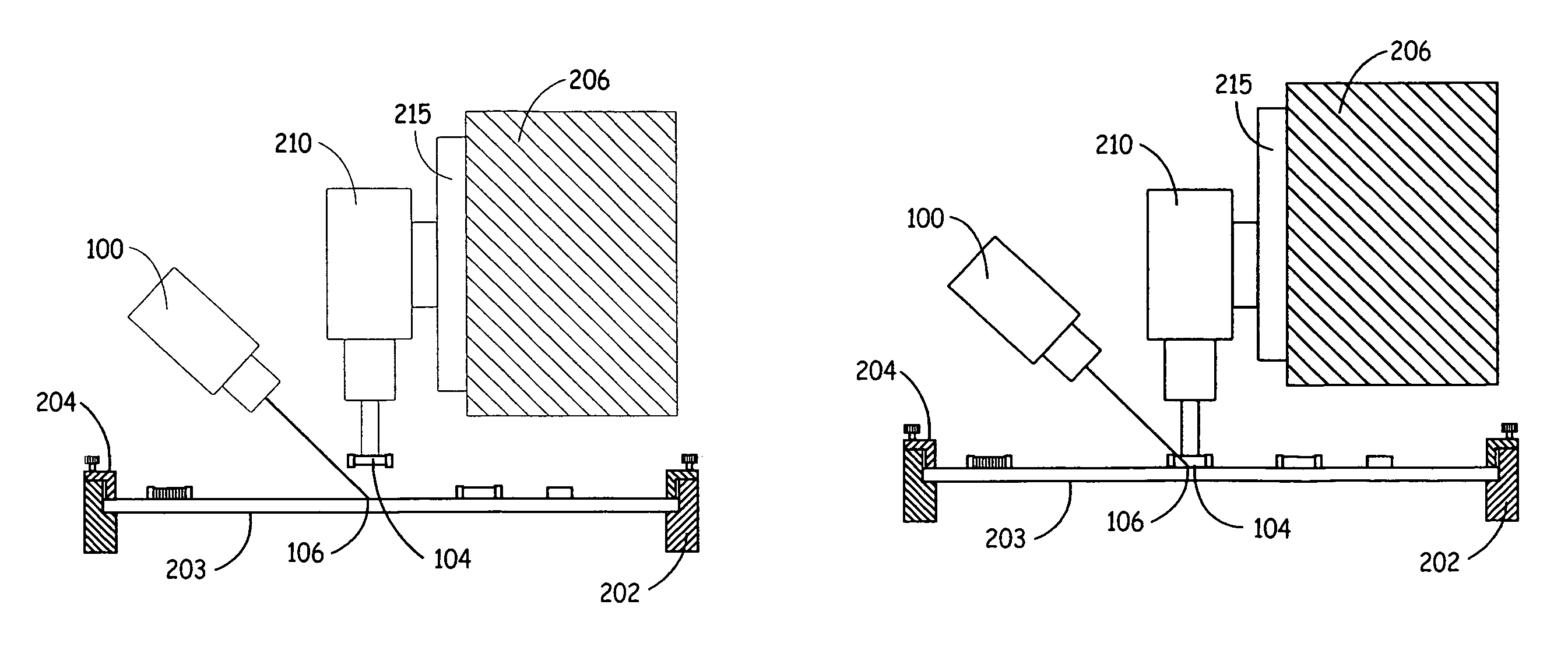
[0032]Embodiments of the present invention generally measure the travel of a pick and place machine placement nozzle and the motion characteristics of the workpiece through the placement process. Since the component is placed on the workpiece with some force to ensure proper adhesion to the workpiece, some deflection of the workpiece is expected during the placement cycle. The placement force is adjusted to ensure that the component is safely placed into the solder paste or adhesive. Placement force is adjusted through a number of characteristics including: choice of spring tension in the nozzle; the length of the nozzle and the amount of over-travel into the board; the rigidity of the board and design; and the placement of the board support mechanisms. With proper adjustment of these characteristics and parameters, high quality placements onto the workpiece can be ensured. To properly adjust these parameters, a method of measuring the workpiece motion and nozzle travel is required....


PUM


Abstract

Embodiments include measuring motion characteristics of the workpiece through the placement process. Since the component is placed on the workpiece with some force to ensure proper adhesion to the workpiece, some deflection of the workpiece is expected during the placement cycle. The placement force is adjusted to ensure that the component is safely placed into the solder paste or adhesive. Placement force is adjusted through a number of characteristics including: choice of spring tension in the nozzle; the length of the nozzle and the amount of over-travel into the board; the rigidity of the board and design; and the placement of the board support mechanisms. With proper adjustment of these characteristics and parameters, high quality placements onto the workpiece can be ensured.

Description

CROSS-REFERENCE TO RELATED APPLICATIONS[0001]The present application is based on and claims the benefit of U.S. provisional patent application Ser. No. 60 / 518,153, filed Nov. 7, 2003, the content of which is hereby incorporated by reference in its entirety.COPYRIGHT RESERVATION[0002]A portion of the disclosure of this patent document contains material that is subject to copyright protection. The copyright owner has no objection to the facsimile reproduction by anyone of the patent document or the patent disclosure, as it appears in the Patent and Trademark Office patent files or records, but otherwise reserves all copyright rights whatsoever.BACKGROUND OF THE INVENTION[0003]Pick and place machines are generally used to manufacture electronic circuit boards. A blank printed circuit board is usually supplied to the pick and place machine, which then picks electronic components from component feeders, and places such components upon the board. The components are held upon the board tem...

Claims


Application Information

Patent Timeline
Patent Type & Authority Patents(United States)
IPC IPC(8): G06K9/00H05K13/04
CPCH05K13/0413H05K13/0812H05K13/04
Inventor BUSHMAN, THOMAS W.MADSEN, DAVID D.HAUGEN, PAUL R.CASE, STEVEN K.GAIDA, JOHN D.MADSEN, M. HOPE
Owner CYBEROPTICS
Why Eureka
Try Eureka