
Automatic orientation determination for ECG measurements using multiple electrodes

a technology of ecg and orientation determination, applied in the field of implantable medical devices, can solve problems such as potential life-threatening events, bradycardia producing a heart rate that is too slow to maintain adequate circulation, and cardiac arrhythmia impairing cardiac efficiency

Inactive Publication Date: 2010-04-27
CARDIAC PACEMAKERS INC
View PDF379 Cites 41 Cited by
  • Summary
  • Abstract
  • Description
  • Claims
  • Application Information

AI Technical Summary

Benefits of technology

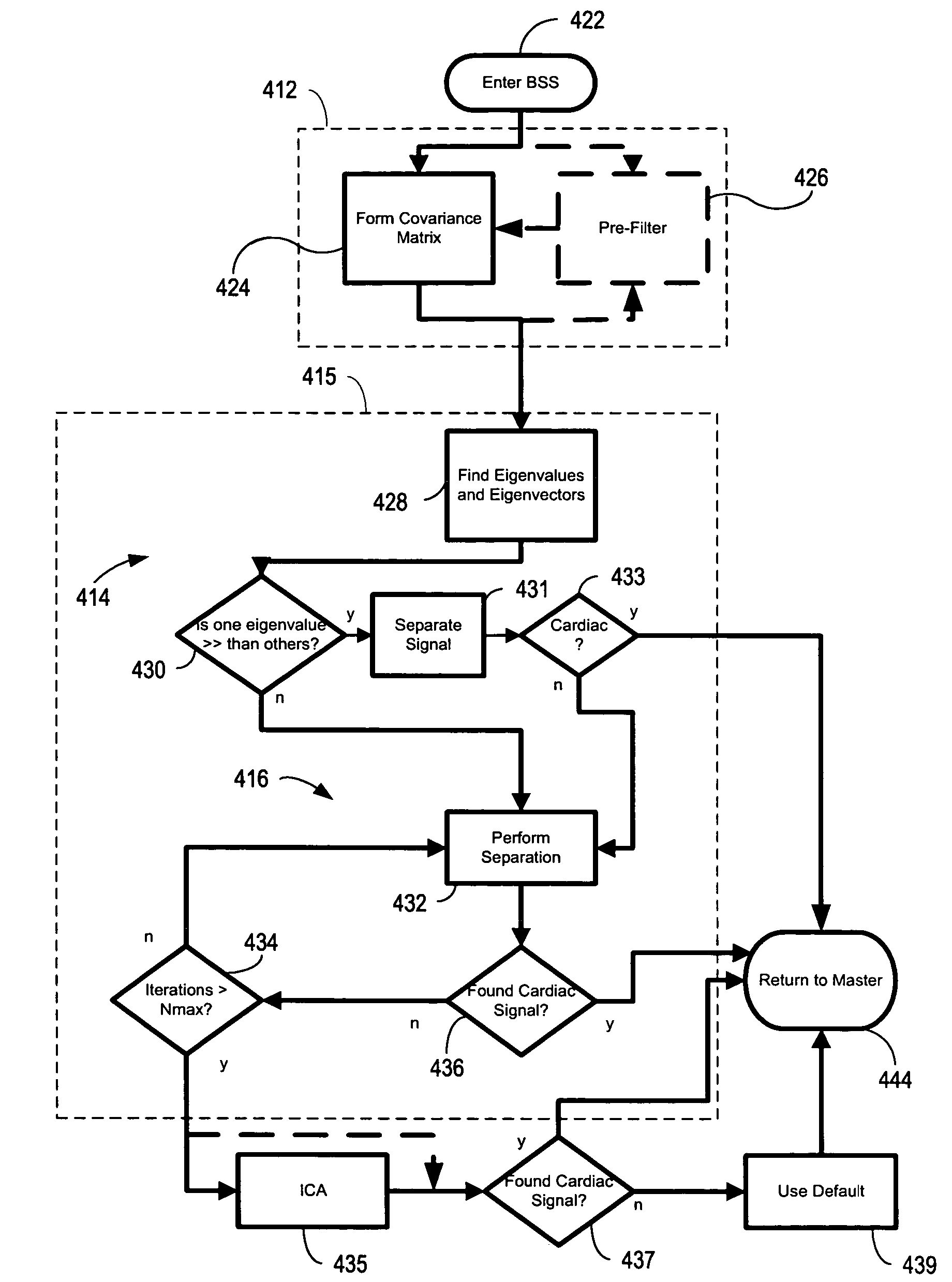
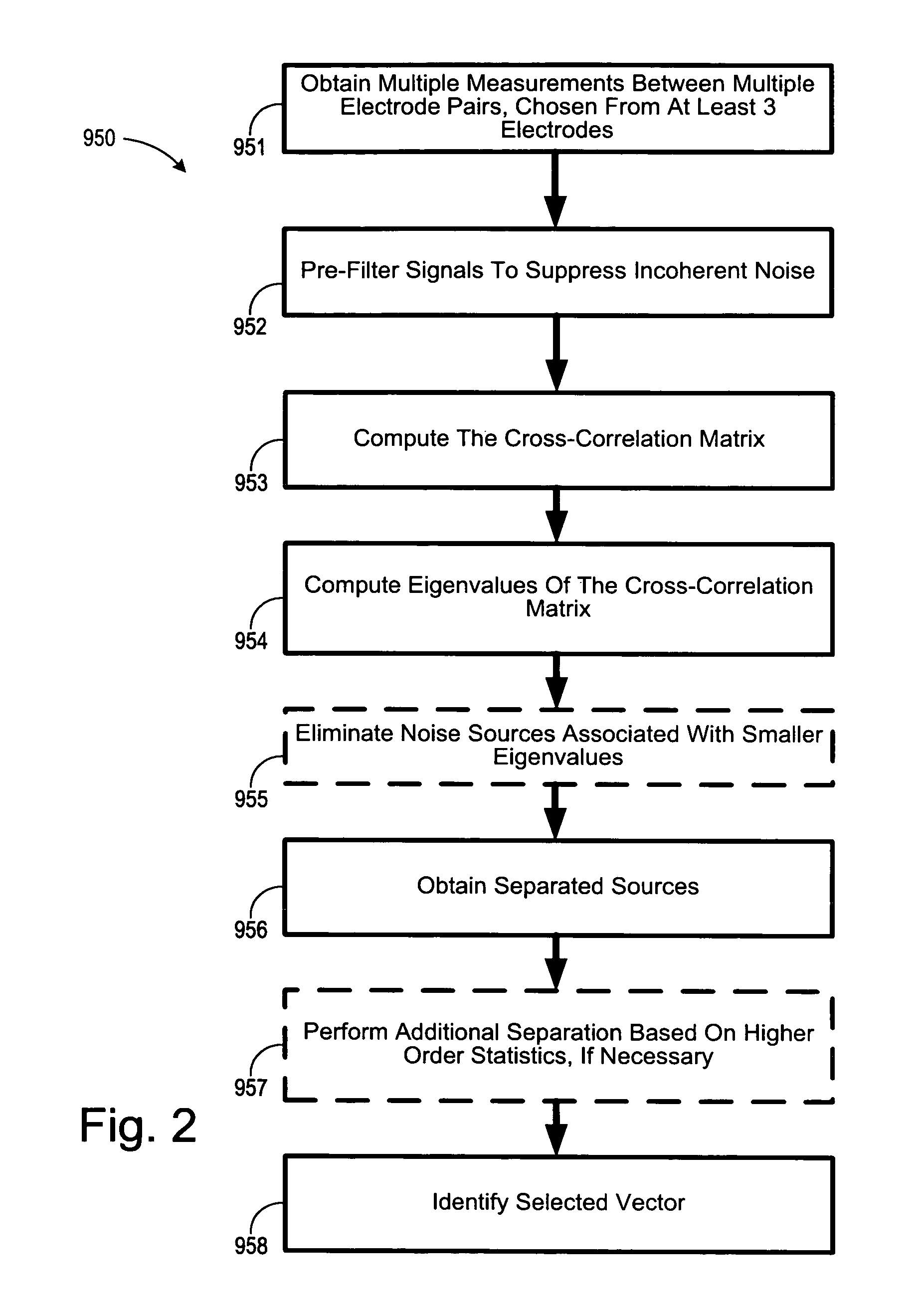
The present invention is about cardiac monitoring and stimulation methods and systems that provide these capabilities. The invention involves using multiple electrodes to sense and separate signals from the heart, allowing for the monitoring and treatment of cardiac conditions. The invention also includes a controller, memory, and signal processor to perform source separation and update the target vector with subsequent signals. The invention can be used in implantable medical devices or external devices, and can be coupled with wireless communication to facilitate data transfer. The technical effects of the invention include improved accuracy and efficiency in cardiac monitoring and treatment.

Problems solved by technology

Cardiac arrhythmia impairs cardiac efficiency and may be a potential life-threatening event.
Bradycardia produces a heart rate that is too slow to maintain adequate circulation.
Besides being hemodynamically inefficient, the rapid contractions of the atria may also adversely affect the ventricular rate.
The rapid and erratic excitation of the ventricular tissue prevents synchronized contractions and impairs the heart's ability to effectively pump blood to the body, which is a fatal condition unless the heart is returned to sinus rhythm within a few minutes.

Method used


Image

  • Automatic orientation determination for ECG measurements using multiple electrodes
  • Automatic orientation determination for ECG measurements using multiple electrodes
  • Automatic orientation determination for ECG measurements using multiple electrodes

Examples


Embodiment Construction

[0029]In the following description of the illustrated embodiments, references are made to the accompanying drawings, which form a part hereof, and in which is shown by way of illustration, various embodiments in which the invention may be practiced. It is to be understood that other embodiments may be utilized, and structural and functional changes may be made without departing from the scope of the present invention.

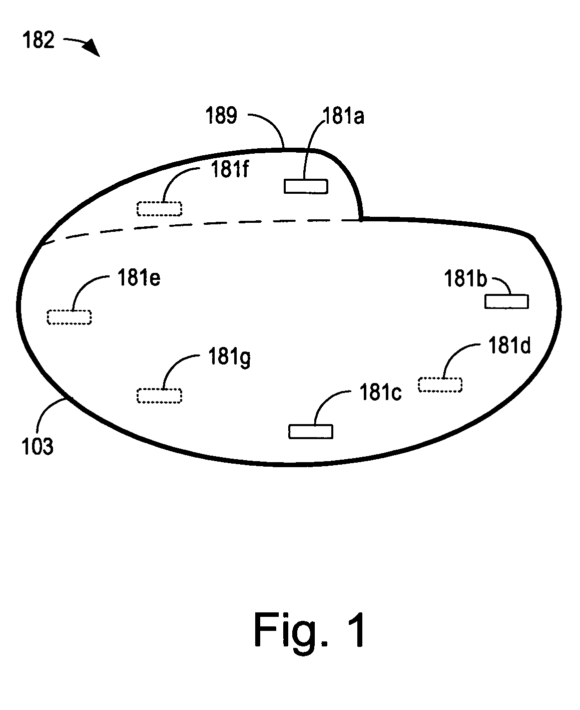
[0030]An implanted device according to the present invention may include one or more of the features, structures, methods, or combinations thereof described hereinbelow. For example, a cardiac monitor or a cardiac stimulator may be implemented to include one or more of the advantageous features and / or processes described below. It is intended that such a monitor, stimulator, or other implanted or partially implanted device need not include all of the features described herein, but may be implemented to include selected features that provide for unique structures and / or ...


PUM


Abstract

Cardiac monitoring and / or stimulation methods and systems provide monitoring, defibrillation and / or pacing therapies. A signal processor receives a plurality of composite signals associated with a plurality of sources, separates a signal using a source separation algorithm, and identifies a cardiac signal using a selected vector. The signal processor may iteratively separate signals from the plurality of composite signals until the cardiac signal is identified. The selected vector may be updated if desired or necessary. A method of signal separation involves detecting a plurality of composite signals at a plurality of locations, separating a signal using source separation, and selecting a vector that provides a cardiac signal. The separation may include a principal component analysis and / or an independent component analysis. Vectors may be selected and updated based on changes of position and / or orientation of implanted components and changes in patient parameters such as patient condition, cardiac signal-to-noise ratio, and disease progression.

Description

FIELD OF THE INVENTION[0001]The present invention relates generally to implantable medical devices employing cardiac signal separation and, more particularly, to cardiac sensing and / or stimulation devices employing automated vector selection from multiple electrodes.BACKGROUND OF THE INVENTION[0002]The healthy heart produces regular, synchronized contractions. Rhythmic contractions of the heart are normally controlled by the sinoatrial (SA) node, which is a group of specialized cells located in the upper right atrium. The SA node is the normal pacemaker of the heart, typically initiating 60-100 heartbeats per minute. When the SA node is pacing the heart normally, the heart is said to be in normal sinus rhythm.[0003]If the heart's electrical activity becomes uncoordinated or irregular, the heart is denoted to be arrhythmic. Cardiac arrhythmia impairs cardiac efficiency and may be a potential life-threatening event. Cardiac arrhythmias have a number of etiological sources, including t...

Claims


Application Information

Patent Timeline
Patent Type & Authority Patents(United States)
IPC IPC(8): A61B5/04A61B5/00A61B5/0402A61B5/042A61N1/365A61N1/375G06K9/62
CPCA61B5/0006A61B5/0031A61B5/04011A61B5/7217G06K9/624A61B5/7207A61N1/3756A61B5/0422A61B5/341A61B5/287G06F18/2134
Inventor ZHANG, YIBROCKWAY, MARINARICCI, CARLOS ALBERTOHEIL, RONDAUM, DOUGLAS R.SWEENEY, ROBERT J.MCCABE, AARON
Owner CARDIAC PACEMAKERS INC
Learn More