
Position based velocity estimator

Active Publication Date: 2010-04-27
TRIMBLE NAVIGATION LTD
View PDF20 Cites 12 Cited by
  • Summary
  • Abstract
  • Description
  • Claims
  • Application Information

AI Technical Summary

Benefits of technology

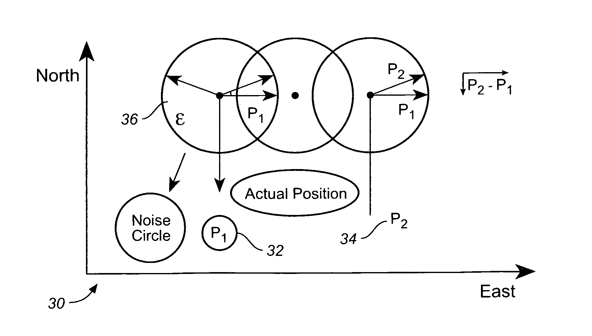
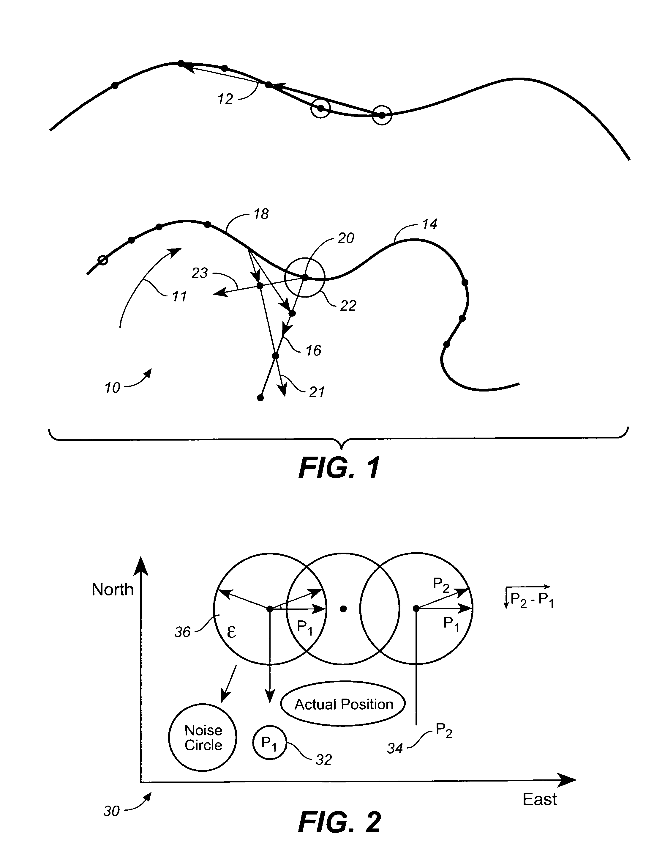
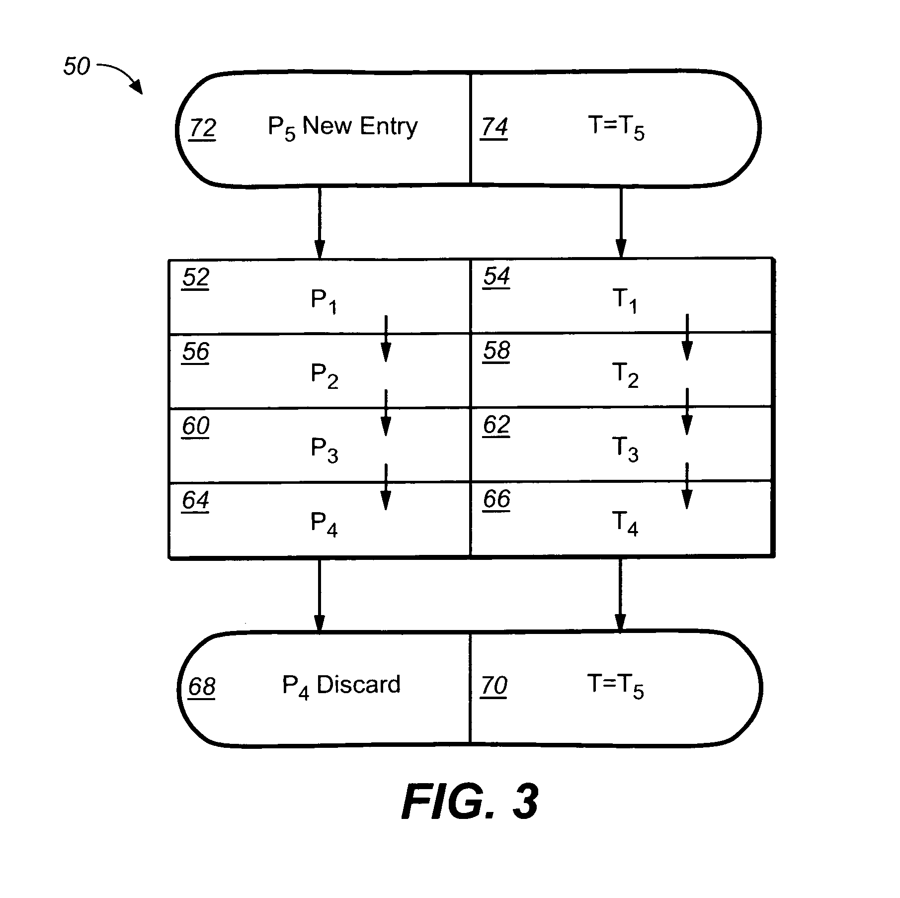
[0015]In one embodiment of the present invention, the step (C1) further comprises the following steps: the step (C1, 1) of repeating step (C1) for a substantially sufficient number of pairs of stored rover points; and the step (C1, 2) of minimizing an error in determination of the current heading of the rover by optimizing the step (C1, 1) for a plurality of obtained headings of the rover. In another embodiment of the present invention, the step (C2) further comprises the following steps: the step (C2, 1) of repeating the step (C2) for a substantially sufficient number of the stored rover points; and the step (C2, 2) of minimizing an error in determination of the current heading of the rover by optimizing the step (C2, 1) for a plurality of obtained headings of the rover.

Problems solved by technology

This is an unacceptable level of noise.

Method used


Image

  • Position based velocity estimator
  • Position based velocity estimator
  • Position based velocity estimator

Examples


Embodiment Construction

[0034]Reference will now be made in detail to the preferred embodiments of the invention, examples of which are illustrated in the accompanying drawings. While the invention will be described in conjunction with the preferred embodiments, it will be understood that they are not intended to limit the invention to these embodiments. On the contrary, the invention is intended to cover alternatives, modifications and equivalents that may be included within the spirit and scope of the invention as defined by the appended claims. Furthermore, in the following detailed description of the present invention, numerous specific details are set forth in order to provide a thorough understanding of the present invention. However, it will be obvious to one of ordinary skill in the art that the present invention may be practiced without these specific details. In other instances, well known methods, procedures, components, and circuits have not been described in detail as not to unnecessarily obsc...


PUM


Abstract

A method of determining speed and heading of a rover / rover having one degree of freedom comprising the following steps: (A) determining a rover position coordinates using at least one source of a radio position measurements; (B) storing a set of statistically different rover points in a memory block, and (C) using a subset of rover points including a plurality of stored rover points and a current rover point to determine a speed and a heading of the rover. It is assumed that each rover point comprises a time Epoch and a rover position determined at time Epoch, and that each pair of statistically different rover points comprises two rover positions separated by a statistically significant distance.

Description

BACKGROUND OF THE INVENTION[0001]1. Field of the Invention[0002]The present invention is in the field of control systems, and more specifically, is in the field of position based velocity estimation.[0003]2. Discussion of the Prior Art[0004]When a rover is moving quickly, the conventional approach is to take a fix as often as possible (like every 100 to 200 msec) and to calculate an instantaneous rover direction vector based on two rover positions: a current rover position, and a referenced future rover position as to where it should be at certain point in time. This approach works well when the rover is moving along at a relatively moderate speed so that the distance between fixes is greater than the error in the fix determination. For example, at 99 inches per second, or at 9 km / hour, if one takes a fix 10 times per second, the rover has moved about 10 inches between fixes. If a fix accuracy is 2 inches, then the position fix “noise” is about 20%. This is an acceptable level of no...

Claims


Application Information

Patent Timeline
IPC IPC(8): G01C21/00
CPCG01P3/64G01S19/41G01S19/52G01S19/49G01S19/44G01S5/017
Inventor PEAKE, JOHN WILLIAM
Owner TRIMBLE NAVIGATION LTD
Learn More